

Hi all,
I hope someone can offer some advice, as I'm not that familiar with Lithium batteries and BMS's.
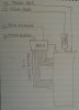
I have a lithium battery here that I have taken apart. The connections are as follows:
Before I blow anything up, can anyone confirm my assumptions:
1. Battery output is via the the thick Red/Black pair.
2. If 1 above is true then BMS must cutout on negative side.
3. Charging must be via thick black and thin red, via thermistor.
4. What is the thin orange for?
Appreciate any input,
Thanks
I hope someone can offer some advice, as I'm not that familiar with Lithium batteries and BMS's.
I have a lithium battery here that I have taken apart. The connections are as follows:
Before I blow anything up, can anyone confirm my assumptions:
1. Battery output is via the the thick Red/Black pair.
2. If 1 above is true then BMS must cutout on negative side.
3. Charging must be via thick black and thin red, via thermistor.
4. What is the thin orange for?
Appreciate any input,
Thanks


