Help! Battery problem

electricorange

Finding my (electric) wheels
Sep 9, 2021
23
0
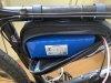
Hi all! I fairly recently built an e-bike based around the Tongsheng TSDZ2. See the link below for the build thread.


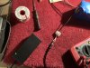
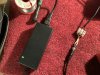
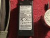
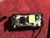
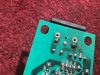
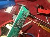
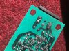
Up until a week or so ago it was going swimmingly. However following some modifications to the battery connectors the battery no longer wants to charge. My best guess is that I overheated the cables while soldering the new connector on, although it's possible that it's a coincidence. I thought I had successfully charged it after the mod, but after a good ride (where I ran the battery flat) the charger refused to charge it at all.

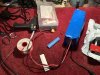
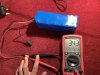
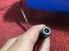
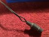
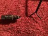
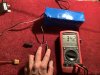
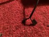
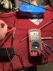
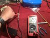
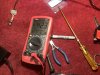
My attempts to troubleshoot it have thus far been limited to measuring the output voltage from the battery (which is healthy, especially given that it is flat) and then a not very well thought out attempt to check for continuity at the DC charge socket, which resulted in me shorting the socket out with the multimeter probe, cue sparks, smoke and a melted socket, plus a melted multimeter probe. Pretty impressive for a dead battery - it has given me a new found respect for and fear of the unit.

Not sure what my next step is. Obviously I could replace the battery but the broken one is barely used...
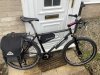
43929
 

Nealh

Esteemed Pedelecer
Aug 7, 2014
19,991
8,173
60
West Sx RH
Show us the battery.
 

soundwave

Esteemed Pedelecer
May 23, 2015
15,972
6,292
imo you fried the bms charging circuit so will need to get to the bms to see what is going on.
 

Nealh

Esteemed Pedelecer
Aug 7, 2014
19,991
8,173
60
West Sx RH
Have you changed the charge connector for a new one ?
 

soundwave

Esteemed Pedelecer
May 23, 2015
15,972
6,292
you need to check the voltage of the cells as might now be so low it wont charge esp if you have shorted the charging cable.


it only takes one cell to get so low the bms then wont charge the pack.
 

Nealh

Esteemed Pedelecer
Aug 7, 2014
19,991
8,173
60
West Sx RH
You will have to cut open the shrink then, could also just be a loose or bad charge wire connection. New shrink wrap isn't dear to buy.

Neal's tip:
For checking charge voltage on a female DC type jack with centre v+ pin, simply use a DC Male pin (with screw terminals) to push in and measure voltage from the wire inputs or screw terminals.

Like these, they remove the chance of fireworks occurring. I use these all the time on my battery builds, the screw terminal are always available to use for voltage measuring.
12V DC Power Male Female Power Jack Plug Connector Solderless Adapter Socket DIY | eBay
 
  • Like
Reactions: electricorange

electricorange

Finding my (electric) wheels
Sep 9, 2021
23
0
Thanks for the input so far. Off to work now but hopefully I'll have time to have a play with it this evening. Have ordered one of those DC plugs too - top tip - thanks.
 

electricorange

Finding my (electric) wheels
Sep 9, 2021
23
0
Ok, well for starters voltage measured at the (gingerly removed) charge socket C67CDDAF-94DB-4197-9991-875DB6801115.jpegEC2A4D71-C694-4F0A-94F0-25BCB7218835.jpegFB7D5856-D2E6-4C6A-9C64-CB5A9FA786BF.jpeg98DB81D7-A737-4159-8283-F070ACBB6B0C.jpeg310D7A02-8A1E-492D-817D-C732F6E810BE.jpegD7DA69B4-392A-470F-A86D-946F20D456EB.jpegand the output. Also a pic of the melted DC socket for your viewing pleasure.

Before I rip the shrinkwrap off, what are the chances the charger is at fault? And how to check?
 

Nealh

Esteemed Pedelecer
Aug 7, 2014
19,991
8,173
60
West Sx RH
The - 34.2 is fine and is almost equal to that of the discharge voltage, all the - means is you have the probes on the wrong pole and polarity is reversed. So reverse the probes and then mark the V+ wire so you know which it is, one of the Black charge wires has a secondary White stripe on it to denote it as V+. Screw one of those new Green/Black screw jacks on and charge to see if it works.
 

electricorange

Finding my (electric) wheels
Sep 9, 2021
23
0
The - 34.2 is fine and is almost equal to that of the discharge voltage, all the - means is you have the probes on the wrong pole and polarity is reversed. So reverse the probes and then mark the V+ wire so you know which it is, one of the Black charge wires has a secondary White stripe on it to denote it as V+. Screw one of those new Green/Black screw jacks on and charge to see if it works.
Thanks, yes I'm aware of basic electronics (i.e. polarity) - apologies for being lazy with the meter.

New jack has not yet arrived so I bodged something up. Charger connected. As before it stays on green "charge full/disconnect" and won't go in to charge mode (red).

I'm beginning to suspect the charger but not sure how to prove it other than trying a replacement (which I don't own). Note that the green light illuminates irrespective of whether mains is connected to the brick.517EF5F1-679E-4DC5-B7EC-76BAA64E548C.jpeg620EFA4A-39FF-42B4-BD30-56EE0481F719.jpeg9CA92B7C-AAC6-4107-9CC4-CB22EC03D915.jpeg
 

electricorange

Finding my (electric) wheels
Sep 9, 2021
23
0
I can't see anywhere where you checked the 42v charger voltage.
The charger is not providing 42v. I haven't photographed it but I did take a measurement just now to double check.

I'd assumed (correct me if I'm wrong) that the brick is designed not to provide a charge unless it "sees" a battery. As long as the LED stays green it doesn't put any voltage out?

Bonus pic of the inside of the charger. Fuses (plug and internal) are both OK. No obvious damage.EB874049-4B6E-4B96-9630-3604763BB9E5.jpeg
 

vfr400

Esteemed Pedelecer
Jun 12, 2011
9,822
3,985
Basildon
If the charger doesn't provide 42v, there's no way it can charge.

Whenever you get a charging problem (no charging), the first thing you do is measure the voltage on the charger's connector and on the socket in the battery. Those two measurements will tell yor where the problem lies 99.834% of the time. There's absolutely no point in going anywhere near the battery if the charger doesn't have the correct voltage (42.0v for 36v batteries) on its connector.

This statement only applies to batteries that connect to the charger with two wires/pins and therefore don't use communications. All the Bosch, Shimano, Yamaha, Brose, etc crank drive bikes use comms, and so do Raleigh bikes, bikes with TranzX systems and bikes with Suntour systems, like the Haalfords carrera ebikes. There's no way to test these chargers or batteries. You have to take them to a deal, who has the comms equipment to talk to the batteries or chargers. All these bikes have an array of pins on the charger, not just a simple jack.
 
  • Like
Reactions: electricorange

electricorange

Finding my (electric) wheels
Sep 9, 2021
23
0
OK, thanks. It would appear that it's time for a new charger. I'm glad I haven't yet pulled the battery apart as previously suggested... Any recommendations for a decent replacement?

So just to confirm - should my charger should provide 42v whether or not it senses there's a battery connected? I'm fairly sure that when everything was working OK the charger would switch off (green LED) when no battery was connected or after reaching full charge.

Assuming it does need to "see" a battery to switch on is the presence of 34v at the charge socket enough?
 

electricorange

Finding my (electric) wheels
Sep 9, 2021
23
0
I think I've fixed it! And answered my own questions in the process. The only unanswered question is how the hell did that solder joint get in such a mess?

Photos in reverse order, for some reason.
509893FB-861F-4952-A29A-8F2EC3092F42.jpeg7637DA81-B73B-481D-AB1E-E6BBE7246A04.jpeg3DA79031-6341-49E5-A48F-21348AAE0D67.jpeg444C10B8-D70A-4E83-A1F8-3E9CB4159725.jpeg5E2371E8-282B-4188-96CE-3D10A40DAFC8.jpeg
 
Last edited:

vfr400

Esteemed Pedelecer
Jun 12, 2011
9,822
3,985
Basildon
Having seen all the evidence, I'm now going to pass judgement. When you modified your connector, you caused a problem, like a short or polarity issue, so that when you connected the charger, you over-loaded it, which blew that solder joint like a fuse, so you were lucky. If it hadn't blown, the damage could have been a lot worse.
 

electricorange

Finding my (electric) wheels
Sep 9, 2021
23
0
Having seen all the evidence, I'm now going to pass judgement. When you modified your connector, you caused a problem, like a short or polarity issue, so that when you connected the charger, you over-loaded it, which blew that solder joint like a fuse, so you were lucky. If it hadn't blown, the damage could have been a lot worse.
Hmm... It's an interesting theory, but I don't think you're right. There's nothing to suggest that the modified battery connector is causing a fault - it's functioning perfectly.

My theory, ahem, is that there was a dry/poorly soldered joint on the board, or that it was physically damaged by movement of the figure of 8 mains lead (fairly likely given the way the socket is mounted) - which then started arcing - in turn melting the solder and destroying the joint.

In any case there are two fuses protecting the charger - it seems highly unlikely that an overload would randomly blow apart a solder joint and not take out a sensibly rated fuse right next to it.

It's happily charging now. I'm confident that the connection I made is good - carefully soldered and insulated - I personally think it was a red herring and pure coincidence that the charger died shortly after the mod. Note I already mentioned in the OP that, I was satisfied that I had successfully charged it after first doing the mod, the fault appearing after the first test ride...