Bridge from battery to controller

103Alex1

Esteemed Pedelecer
Sep 29, 2012
2,228
67
Been reading d8veh's very helpful guidance on this and also the discussions in ian85's thread.

Before rushing off to heat up a soldering iron and finally conquer my trepidation on that front (or more likely watch the video on how to set up a suitable safe environment for indoor soldering without wrecking the kitchen :p) I wanted to double check I have understood how this works. Photos probably the best way rather than oceans of text :

20130130_234507[1].jpg

20130130_234414[1].jpg

20130130_234649[1].jpg

20130130_234737[1].jpg
 
Last edited:

103Alex1

Esteemed Pedelecer
Sep 29, 2012
2,228
67
Picture 1

The top pic is a mock up of the spare white connector with 2 pins only inserted facing the connector coming out of the controller. The black and red wires feeding in from the right are 12AWG 200degreesC bought off e-bay.

Black to Black and red to red (all thick wires)

Picture 2

This is the other end. At the top is the connector coming out of the battery showing N on the left and L on the right. I am guessing I am matching this in the connector which fits into this i.e. black and red as shown.

Picture 3

Close-up of the white connectors with pins mocked up. I think I have the top pin upside down ? ... sorry - have never done anything like this before so pls don;t assume even the most basic things can be taken as read to be understood lol :eek:

Picture 4

Top view of incoming lead / connector.

Is this right / have I missed anything ? Also do I need to use all 3 pins on the spare white connector or just the 2 which will have wires attached to them.

This is turning into a proper education !
 
D

Deleted member 4366

Guest
You've missed a small piece of wire that needs to loop out the back of the thick red battery wire to the spare spade next to it that will connect to the thin red wire. It's on this bridge that you'd fit a standby switch if you wanted one.


Last edited by a moderator:

103Alex1

Esteemed Pedelecer
Sep 29, 2012
2,228
67
You've missed a small piece of wire that needs to loop out the back of the thick red battery wire to the spare spade next to it that will connect to the thin red wire. It's on this bridge that you'd fit a standby switch if you wanted one.


Been to 3 electrical shops, an automotive shop on the industrial estates and a model making shop this afternoon and not one of them had any thin red wire. :mad: ... obviously not shopping in the right places :eek: I think I may be better off shopping from my desktop and waiting !

Anyhoo ... any e-bay links for suitable thin wire of different colours as coming out of the controller so I can put some into stock ? I am not sure what gauge to look for... the shop assistants all just looked blankly at me.

I also looked for some Deans-type connectors to explore that route but the electrical supply shops had never heard of them and the model making shop out of stock. On the plus side, I did get some shrink wrap stuff for cabling which might come in handy - and some aluminium sheeting, albeit in 3.2mm which might do for brackets. Oh - and a 1/2" x 4' plank of balsa, in the absence of anything else 1/2" left on the shelf, and some mini-clamps.

So not entirely unsuccessful on reflection .. some progress I guess is better than none at all. Now I just need to get some saws and a drill lol. Scroll saw or jigsaw ... wondering which would be most useful :confused: .... there's so much choice of everything these days I end up in a muddled confused heap walking out with nothing !
 
Last edited:
D

Deleted member 4366

Guest
You can strip a bit of wire out of any old mains leads that you have around the house. It doesn't have to be red or thin, although thin is better if you want to put a switch on later.

To shrink the heat-shrink, you can use the shoulder of the soldering iron - where the tip comes out of the body. Just stroke it slowly and gently giving just enought time for it to shrink. Work your way all round to shrink it all over.
 

Old_Dave

Esteemed Pedelecer
Sep 15, 2012
1,211
2
Dumfries & Galloway
Scroll or jig saw, the answers quite simple.... Both.

Depending upon the task at hand each has its strengths and weaknesses.

ImageUploadedByTapatalk1359669358.325205.jpg

ImageUploadedByTapatalk1359669379.608539.jpg

:D


Sent from my iPhone using Tapatalk
 

103Alex1

Esteemed Pedelecer
Sep 29, 2012
2,228
67
Excellent - thanks for that. Plenty of old mains leads in the appliance graveyard box I'm sure....

Are these the Deans connectors you can use in place of the kettle plugs on the lead exiting the battery and connector in pic 2 above ?

5 PAIRS GOLD PLATED GRIP DEANS CONNECTORS T PLUGS | eBay
 

103Alex1

Esteemed Pedelecer
Sep 29, 2012
2,228
67
Scroll or jig saw, the answers quite simple.... Both.

Depending upon the task at hand each has its strengths and weaknesses.

View attachment 4971

View attachment 4972

:D


Sent from my iPhone using Tapatalk
Ho de ho ..... nice work there. Scroll or jig ? Am on the verge of doing the jig actually .... strike up the band ....

Jobs foreseen are :

Woodworking on bike box. Cutting ply and balsa and grooves in internal compartments etc. Can probs use a hacksaw for most of it come to think of it buy anyhoo ...

Cutting brackets out of the aluminium sheeting for light and probably also for box (top mount). Maybe cutting out a charger plate either in aluminium or wood - in the process of trying to work that out still.

Plus a drill required. Yodel yodel yodel failed to deliver my demel tool thing today claiming they came at half 5 when they didn't :rolleyes: ... hopefully tomorrow ... are there any attachments which would fit that and also drill out metal or is it a case of getting a drill too ? I have an electric drill and jigsaw in Devon but they're being used there & there the bike is here so it's yo ho ho back to the piggy bank we go ... again ! lol.
 
D

Deleted member 4366

Guest
Yes. They're also called "T" connectors. The convention is that the vertical side is +ve (red) and the horizontal -ve (black). Always insulate the first side before doing the second if it's on the battery.
 

Old_Dave

Esteemed Pedelecer
Sep 15, 2012
1,211
2
Dumfries & Galloway
Ok.....

A few decent hand saws (maybe 4) and a set of chisels will take care of almost anything you will ever want to do with wood.

Metal, dremel with accessorys and an electric drill, large and small hack saw, decent set of drill bits and a few files (1 bastard) should take things

That's the sensible starting list, but I could go on to lathes bandsaws pillar drill loads of clamps (you never have enough clamps) hole saws taps and dies glues sealants different grades of locktite grinders welders and on and on and on


Sent from my iPhone using Tapatalk
 

103Alex1

Esteemed Pedelecer
Sep 29, 2012
2,228
67
Oh for access to a carpentry and metalworking workshop on an hourly basis ... could do so much so easily with it all to hand as you just go look for what seems best for the job :). Hey ho .... will muddle through !!
 

103Alex1

Esteemed Pedelecer
Sep 29, 2012
2,228
67
Right, I have set aside all trepidation and christened the soldering iron. Connector duly made with bridge wire from a defunkt laptop lead as my first soldering job after practicing on a few bits of power cord wire, watching several videos and making every mistake in the book before going for the pins ! The black is shrinkwrap - I overstripped a bit so made it neat.

20130201_044318[1].jpg

20130201_045739[1].jpg

Feeling less intimidated now after that !

The 12AWG lead is blooming hard to crimp in the pins especially with a pair of pliers though ... it's really thick ! The solder did a good job of sealing it all in as a bonus but it was tightly held before I put any solder on. Very easy to push too far in to the pins ... I wound up trimming the end after crimping with a very sharp stanley-type blade and got tiny hairs of wire everywhere :eek: :rolleyes: ... tinned the cut ends well though all over so hopefully all good.

It was quite tricky to be honest - the thin red wire in its pin was straightforward as loads of room but the other 2 (especially the red with the bridge connection) were extremely tight fits and took some work to get the bridge secure on the thick red wire pin with enough clearance to fit in the connector slot.

The pins completely pushed through in the end (just) and can't be pulled out as they are now clipped on the connection side so I think I'm there with this at least :).

Ordered some Deans Connectors off e-bay for the other side to fit to the battery. Will see how I feel about fitting them when they arrive. Can they be used on the battery charger and to replace the kettle pin too or is that not a good idea ?
 
D

Deleted member 4366

Guest
Crikey Alex, it gets later every night. Alt least you'll be able to sleep knowing that you've spent your day (night) learning a new skill.

You can use deans on your charger as well.but they're a little fiddly to connect. If you have your battery in a bag and have easy access for charging and enough room, you can use the supplied kettle connectors. If you want a more permanent solution, you can use either XLRs (micriohone type) or DC power jack and socket. Yo can get all these bits from Maplin, where you can check that they fit together.

3-Pin XLR Chassis Socket : XLR Connectors : Maplin Electronics
3-Pin XLR Plug : XLR Connectors : Maplin Electronics
Single-Hole-Fixing 2.5mm DC Socket : DC Power Connectors : Maplin Electronics
Screw Terminal DC Power Plugs : DC Power Connectors : Maplin Electronics
 

Old_Dave

Esteemed Pedelecer
Sep 15, 2012
1,211
2
Dumfries & Galloway
Can they be used on the battery charger and to replace the kettle pin too or is that not a good idea ?
Its good practice to keep the battery charge / discharge connectors different, it saves mistakes :D
 

103Alex1

Esteemed Pedelecer
Sep 29, 2012
2,228
67
Crikey Alex, it gets later every night. Alt least you'll be able to sleep knowing that you've spent your day (night) learning a new skill.
It's the only time I can take over the kitchen for my projects ;) .. and have to clear it all up before bed to avoid a 'domestic' ... so it's nice to finish a job if I start one. The feel-good factor compensated for the 2 1/2 hours' sleep !

You can use deans on your charger as well.but they're a little fiddly to connect. If you have your battery in a bag and have easy access for charging and enough room, you can use the supplied kettle connectors. If you want a more permanent solution, you can use either XLRs (micriohone type) or DC power jack and socket. Yo can get all these bits from Maplin, where you can check that they fit together.

3-Pin XLR Chassis Socket : XLR Connectors : Maplin Electronics
3-Pin XLR Plug : XLR Connectors : Maplin Electronics
Single-Hole-Fixing 2.5mm DC Socket : DC Power Connectors : Maplin Electronics
Screw Terminal DC Power Plugs : DC Power Connectors : Maplin Electronics
Fantastic - great to know there are options. It's making the box idea with a permanent build seem more do'able. On that front, been thinking a lot on what, where and how. On a permanent installation I really should plan everything right and build well so this is actually very timely to have a recap.

I am thinking now that an insert panel along the edge of the box facing the rear wheel below the battery would be the most discreet location for charging point. Leaves the sides flush although I'd probably have one removeable anyway for emergencies but will come back to that.

The "control panel" let's call it could be either aluminium or wood. If the box is covered in silver solarfilm or similar either should be OK. These are the outlets which immediately spring to mind which ideally could be located there :

1) Battery charge socket

A waterproof connector would be best ... perhaps the screw-in type if so as would save having to try to recess and cover the panel itself.

2) USB socket - for cycle analyst, speedict or similar output / input (unless that is wireless :confused:)

Would something like this work ... or is this the wrong way round :confused: :) :

Clarion CCA-USB | eBay

3) Master on/off standby switch for battery

4) If I was trying to be really fancy the barrel for something like Frank's key-operated 2-mode switch to turn bike on to legal mode (position 1) and derestricted mode (position 2).

Also thinking about the motor cable and throttle cables and wondering whether these could connect here via screw-in type plugs rather than go into the 'void' through a hole in the box.

Not all of this may be possible / advisable (might not be space aside from anything else !), but would be great to get the voices of experience to advise and work it out.
 
D

Deleted member 4366

Guest
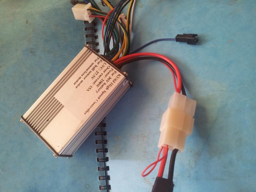
The new Speedict does everything by bluetooth, so you don't need a USB out anymore. The controller has a speed restriction function on it via the white wires. You can join them with a switch to switch on/off the speed restriction, but that doesn't make it legal unless the switch is inaccessible, so a waste of time bothering with it.
If you want to have a go at making one of these remote main switches so that you can just use a small toggle switch, I can send you a PCB, the resistors and capacitor, but you'd have to buy your own FETs. I only have genuine ones that are expensive, but you can buy these counterfeit ones that work OK for the switch:
10 PCS IRFB4110 FB4110 TO-220 POWER MOSFETS Transistor /FREE Registered Mail | eBay


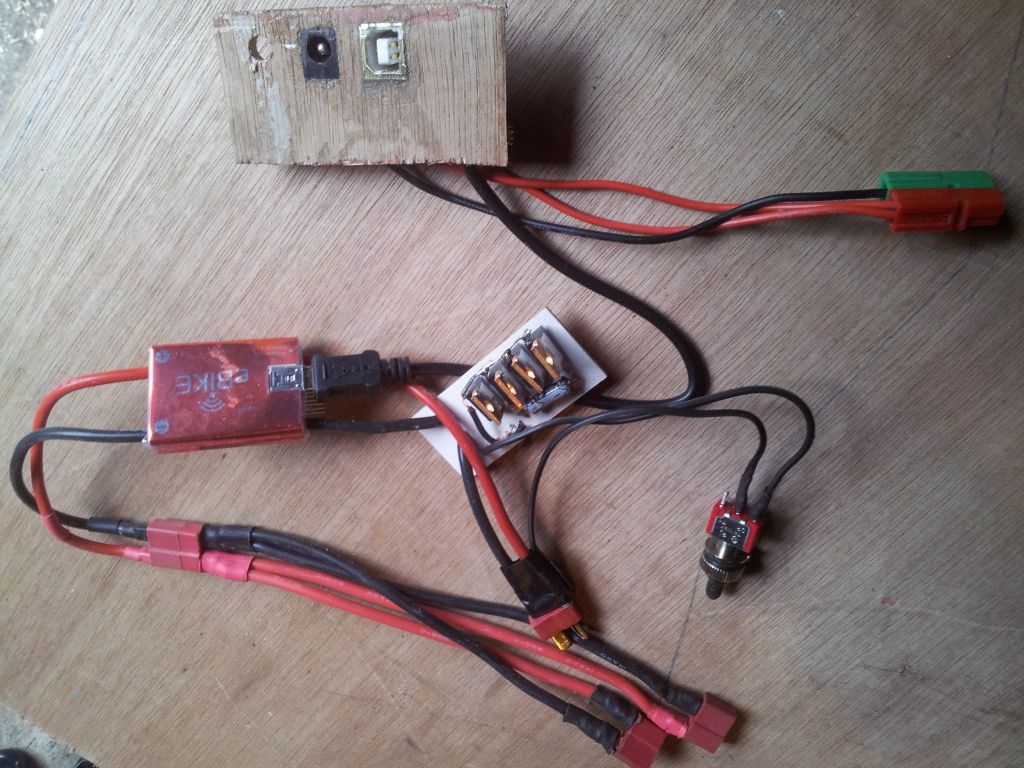
The electronic switch is the whitish thing in the middle, and the battery Deans connector is underneath it. You can see my DC charging jack that connects to the battery charging wires. The little hole to the left is for the toggle switch, which works as the main on/off. The whole panel was glued in underneath the 1.6mm top skin and is covered by a removable panel. The Deans connector underneath the Speedict is for the controller, except that I need that additional two-into-one arrangement because there's two controllrs on this bike.

If you thread the motor wires through brfore fitting the hall sensor connector block, you don't need a big hole. Also, the hole will be in the very bottom, so no water will come in, and if it did, it would fall back out.
You need a hole at the top-front for the throttle and maybe Speedict speed sensor. If you remove the throttle white connector, you can have a small hole, which can be sealed with a bit of silicone afterwards.
 

103Alex1

Esteemed Pedelecer
Sep 29, 2012
2,228
67
OK - many thanks and yes please on the PCB, resistors and capacitor :). I will study the picture with more bits in front of me and try to follow it step by step ... and PM you the address.

On the FETs, take it I need 4 of them ... are these the same things ? Shipping usually quicker from USA but they are a bit more ...

Digi-Key Part Search

Just one initial question - the toggle switch that's coming off the Deans connector ... in context of what I've just made am I going to be undoing the bridge on the white connector and extending the wire to connect to one terminal of the toggle switch ? Honestly it's all a just a big vague fuzz at the moment but I know it will all come together and the pennies drop eventually :p You've got me this far and I'm sure you can get me the rest of the way lol.

Happy boy today as my 3mm plywood sheet finally arrived. I've been putting off another little job for about 2 years because it needs marine ply and the stuff is just about impossible to buy in small quantities never mind the cost of it. I put it together with this job and decided to finally splash out (no pun intended) and get a sheet. The pattern should be very economic so I know I'll have plenty. Only thing is the grain is so gorgeous it seems a shame to cover it over :eek: !!!


Love this stuff ... just seeing it makes me want to get the beeswax out lol
 

Old_Dave

Esteemed Pedelecer
Sep 15, 2012
1,211
2
Dumfries & Galloway
I know this sounds wrong... but trust me :p

Spray it with a few light coats of polycarbonate spray paint and the grain will still show (Metalic graphite is best)
 
D

Deleted member 4366

Guest
The digikey search doesn't show anything.
The thin red wire loop that you made is necessary for the controller to give power. If you put a switch on it, it would switch the motor on and off, but not the controller, so, if you left your bike for a day or so, the battery would be flat even when switched off. To avoid that, you need an additional switch between the battery and controller that can manage more than 30 amps. Most can't, so people often disconnect the battery at the end of their ride, which isn't easy if it's inside a box. Now you can see the advantage of the electronic switch. Those FETs that I linked to will be fine. If you want genuine ones, I can supply you with the complete switch for £15.

Covering with Solarfilm takes quite a lot of practice. I've done loads of model aeroplanes, so it was easy for me and I have the special iron. It might be better to use a filler primer and then spray with car paint. Old Dave's idea about the wood grain is good except that all your joints will show through too.
 

103Alex1

Esteemed Pedelecer
Sep 29, 2012
2,228
67
I know this sounds wrong... but trust me :p

Spray it with a few light coats of polycarbonate spray paint and the grain will still show (Metalic graphite is best)
Was hoping someone might say something like that. I'll try to get the cut on a nice bit of grain rather than a crappy bit now :) ... think I might make a mock-up of the box first and then make it off the template.

If I use Polycarbonate spray paint on it should I use some form of clear epoxy over the top too to seal or is that paint completely weatherproof ?

Hmmm on the joints showing point - will see whether they are visible on the sides or if I get away with none by using single panels. If I can colour match an opaque paint it may be possible to spray between masking tape strips to conceal but probably a case of trying out down the line or on a test bit.
 
Last edited: