

hi all just bought a byocycle ibex ebike and was wondering if anyone know how to add a throttle
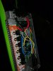
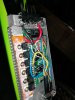
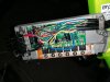
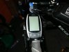
ive added photos of led and controller
many thanks in advance
ive added photos of led and controller
many thanks in advance
Attachments
-
 2.1 MB Views: 12
 -
 3 MB Views: 10
 -
 3.2 MB Views: 11
 -
 1.6 MB Views: 11


