Controller Light Output - Uses?

Nealh

Esteemed Pedelecer
Aug 7, 2014
20,130
8,230
60
West Sx RH
Hi @Nealh , sorry to barge in but also looking at getting a KT 17A to run at 36v with two light outputs. One from a 9pin 1t5 julet cable to front and a separate julet 2pin from the box.
Is the 2a max a standard in KT controllers per light output? Also, is this drawn from the total controller current or is it a passthrough from battery?
It seems it would be managed by controller but in this case if I'm in PAS6 and turn on both lights I should expect in best case scenario a current drop of max 2x 2a. Is this right?

Thanks for your help!
The current drawn is the rating of the Julet pin outs/wiring as in the specs from Julet. from what I have see the controller current output for lights is less and maybe only about 1a.
The dedicated light output afaik runs from a separate line with some KT's also having a separate smaller pcb .
 
Last edited:
  • Like
Reactions: MSG76

MSG76

Pedelecer
Jun 29, 2020
30
6
The current drawn is the rating of the Julet pin outs/wiring as in the specs from Julet. from what I have see the controller current output for lights is less and maybe only about 1a.
The dedicated light output afaik runs from a separate line with some KT's also having a separate smaller pcb .
Thanks @Nealh ! Didn't know julet wires specs. I'm asking the lights company (Contec) as well for current draw specs. Both front and rear run at 6-48v. Front light is supposedly 120 lumens (6-48v) so I'm guessing around 5w / 800mA and I should be fine. It's great to know it's a separate power line! Can't wait to have it all in one simple cable at a push of one single button :)
 

MSG76

Pedelecer
Jun 29, 2020
30
6
The current drawn is the rating of the Julet pin outs/wiring as in the specs from Julet. from what I have see the controller current output for lights is less and maybe only about 1a.
The dedicated light output afaik runs from a separate line with some KT's also having a separate smaller pcb .
Hey @Nealh,
hope you're feeling better today from the incident!

So today got the controller and I'm a bit scared of plugging the lights without some testing before. There are two outputs from controller (on board these are brown and yellow wire) It seems the yellow wire only goes through a 51kΩ smd resistor.

[Edited]
My battery is 36v and just measured the lights with a multimeter on 200mA, front light is continuous 95.6mA, rear light has a stop function which doubles LED's so peaks at 19mA +/- and stays continuous on regular one led at 5.6 mA.

I'm trying to figure this out before connecting it and burning the circuit :D

Can any one help figure out if this circuit can hold over 100mA at peak?
Would it be 100mA per output or for both?
 

Attachments

Last edited:

MSG76

Pedelecer
Jun 29, 2020
30
6
Having successfully installed my new controller and KT-LCD5 display, I'm exploring the 'Light Output' connection on the controller.

It's a 2-pin red Julet connector and when the 'lights on' function is activated from the LCD5 display, the 2 pins have the main battery voltage present.

  • Now, what exactly can you do with this output?
  • The physical pin size is very small so one can't imagine much current can be passed (so what are the current limitations of the connector and indeed the controller?),
  • and what lighting systems use such a (relatively) high voltage?
  • Do you use the output to switch something else via a relay or other circuit?
So I'd be very interested to know what others might use this particular output for?

Many thanks in anticipation, cheers, B4t
View attachment 37266

If you want my advice I was having the same questions. And specially wanting to know how to go about it before burning ny lights or the controller circuit.

When you open the box search for the circuit by following the cathode. Mine had a small pcb with a 510 Ohm smd resistor regulating the output voltage.
I emailed KT which confirmed the pcb only could output 70mA, which is nothing. I soldered a 100 Ohm 5W ceramic resistor in parallel and just tested it today. It works and was outputting 106mA easily.

If you want to lower voltage at some point can always build a voltage divider circuit with two equal value resistors. It's very easy!

Hope it goes well. Best of luck!
 

Attachments

  • Like
Reactions: Bikes4two

Bikes4two

Esteemed Pedelecer
Feb 21, 2020
895
397
Havant
Thanks for that info @MSG76 - although I've now bought the front and rear lights, I've yet to install them - before I do, 'll check what current each light draws and maybe modify the PCB if needed.
 
  • Like
Reactions: MSG76

MSG76

Pedelecer
Jun 29, 2020
30
6
Thanks for that info @MSG76 - although I've now bought the front and rear lights, I've yet to install them - before I do, 'll check what current each light draws and maybe modify the PCB if needed.
Glad I could help! :) But if you want to lower resistance to the max use a similar value resistor. In my case the 510 is a 51Ω, if I had soldered another 51Ω in parallel resistance would decrease by half thus increasing current by double.
Make sure to choose resistors of 1Watt or above
 
  • Like
Reactions: Bikes4two

Bikes4two

Esteemed Pedelecer
Feb 21, 2020
895
397
Havant
  • Well, today as a quick check, I connected up my recently purchased front light to the 2-pin 'light output' connection from the KT controller.
  • The voltage on the connector without the light connected was 40.5v but once the light was powered up, the voltage dropped to just 5.5v, which given the observations made by @MSG76 above, wasn't too much of a suprise.
  • A disappointment though, in that the 'light output' connection has limited use.
  • I've yet to determine what current the rear light draws, but I can see that I am going to have to make up a simple circuit that uses the 'light output' to trigger a relay or Mosfet (or similar) to control a higher powered lighting circuit.
  • Before I break out my Vero board, I'm wondering if there is something already made out there like a simple solid state relay working around 36v-40v to take a 1A load? (eBay here I come).
  • So anyone with useful pointers or ideas on a simple solution to this lighting issue, I'd be very pleased to hear about them.
Cheers, B4t

38430

38433
 
Last edited:

MSG76

Pedelecer
Jun 29, 2020
30
6
You can measure the current if your multimeter allows it to. It should have another red plug (fused or not) and an Ω or Amp setting. Connect the negative and intercept the positive with red lead onto power supply lead and negative on the light positive lead. This will read current.
You can also always try something similar to this, a dc to dc step down isolated converter which will give you plenty of current as lights seem to be multi-voltage:

Best of luck! ;)
 
  • Like
Reactions: Bikes4two

Bikes4two

Esteemed Pedelecer
Feb 21, 2020
895
397
Havant
Thanks for that @MSG76 - I'm fine with basic electronics so I understand what you are saying about measuring the current for each of the lights that I have.

For me, I will want to utilise the KT Controller 'light output' to switch the lights on and off via the KT-LCD5 display function.

The SSR option with an additional fuse is my favoured route at the moment. There are plenty of SSR offerings on ebay and Ali Express for instance - it'll be a case of choosing something that is easy to install in the space(s) that I have.
 
  • Like
Reactions: MSG76

vfr400

Esteemed Pedelecer
Jun 12, 2011
9,822
3,986
Basildon
I can't understand why you would want to do all that when you can connect the lights directly to the battery with a simple switch.

It might be worth checking that the transistor in the controller is still switching before you do anything. They normally blow when you connect a light like that.
 
  • Like
Reactions: Bikes4two

Nealh

Esteemed Pedelecer
Aug 7, 2014
20,130
8,230
60
West Sx RH
My KT 6 fet 17 & 20a has a dedicated horn & lighting wire connections, it shows either 36 or 48v depending on the battery used. The 100 lux front light I have from Onature/Aliexpress with an internal step down converter works with no issues as does a wired 36v rear light, they are both wired in parallel and simply work off a Wuxing light switch n the handle bars.
 

jarob10

Esteemed Pedelecer
Jan 22, 2017
270
83
51
Uk

Bikes4two

Esteemed Pedelecer
Feb 21, 2020
895
397
Havant
Thanks for the feedback @vfr400

I can't understand why you would want to do all that when you can connect the lights directly to the battery with a simple switch.
Fair comment for those who like or need to keep things absolutely simple.

However, I would prefer to use the KT LCD5 built-in light switching function rather than find a suitable switch and run unnecessary cables from/to the switch/battery (and I'd only connect to the battery via a suitable fuse, not directly).

More effort required maybe, but if I get my 'design' right using minimal components (now looking at a single MOSFET as a switch rather than an SSR) that can be fitted inside my rack mounted battery box with the minimum of additinal wiring, that will be a far neater solution IMHO.

It might be worth checking that the transistor in the controller is still switching before you do anything. They normally blow when you connect a light like that.
I seem to have got away with that - clearly the 510 ohm current limiting resistor referred to by @MSG76 has saved the day.
 
  • Like
Reactions: MSG76

vfr400

Esteemed Pedelecer
Jun 12, 2011
9,822
3,986
Basildon
Thanks for the feedback @vfr400


However, I would prefer to use the KT LCD5 built-in light switching function rather than find a suitable switch and run unnecessary cables from/to the switch/battery (and I'd only connect to the battery via a suitable fuse, not directly).

More effort required maybe, but if I get my 'design' right using minimal components (now looking at a single MOSFET as a switch rather than an SSR) that can be fitted inside my rack mounted battery box with the minimum of additinal wiring, that will be a far neater
Your logic seems flawed to me. You concept is to use the switch in the LCD to work another switch to operate the light. That requires extra wiring over what an independent switch would require so it's not minimal. You will still need to run cables from/to the switch/battery. The only difference is that it's an electronically operated switch instead of a manual one.

The only way it would make sense to me is if you were able to run the lights directly from the controller, but the power provided isn't sufficient to run a decent headlight
 
  • Like
Reactions: atheo and Bikes4two

Bikes4two

Esteemed Pedelecer
Feb 21, 2020
895
397
Havant
@vfr400
Your logic seems flawed to me ....
Obviously I have not explained my idea well enough - let me have another go: (apologies if over simplified :()

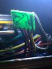
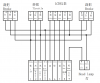
> The KT Controller is located in a separate compartment in the front of the battery box and the battery box is a rear rack mounted affair
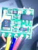
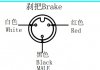
> The KT LCD5 display has as part of it's feature set, the ability to enable lighting via one of the KT controller's leads: the 2-pin Julet connector labelled 'Light Output'
> As now revealed, the current available from the 'Light Output' connector is not sufficient for the lights that I have.
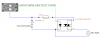
THE PLAN
> is to use the 'Light Output' as a controlling signal for something like a MOSFET or Solid State Relay and these components are to reside in the battery box's front compartment alongside the KT Controller
> The MOSFET (or SSR)
- will pick up the battery supply, via a suitably rated fuse, from the supply line feeding the controller
- the controlling signal will be disconnected from the 2-pin Julet connector lead at the PCB end and fed to the MOSFET to enable it to provide the switched lighting supply
> the switched lighting supply will be connected to the original (and redundant) 2-pin Julet connector to provide a convenient connection to the front and rear lights

So far then, the only additional wiring has been a small amount of wire for the internal connections between the KT Controller and the MOSFET circuitry.

ENHANCED PLAN
> Further, the wiring loom from the front mounted LCD5 display includes along with the brake sensor leads, a throttle lead which I do not use. When I have the controller apart, I will look at the possibility of isolating the leads for the throttle and using them to pass the switched lighting supply to the front of the bike for connection to the front lamp. I will of course need to determine if the throttle lead can take the curent for the front lamp.

In summary, the only extra wires/wiring will be the internal bits as described above, a short length of cable between the battery box's external 2-pin Julet connector and the rear light, and depending on whether I can usitilise the existing throttle cable or not, some other cable for the front light.

The only way it would make sense to me is if you were able to run the lights directly from the controller, but the power provided isn't sufficient to run a decent headlight
.

Functionally I think my plan achieves what you say, albeit with the addition of the MOSFET circuitry, which for me is not much of a challenge (retired electronics engineer, albeit many years ago).
 

MSG76

Pedelecer
Jun 29, 2020
30
6
Just a heads up to anyone who may be thinking of using a KT LCD3 panel to control lights.

Mine is fully working by replacing resistors in pcb and dropping down resistance to 25Ω. Front light is 120Lux, draws 106mA, rear light has brake function so draws around 10mA continuously and 36 mA on auto brake/impact sensor. Both work fine, no smoke no burnt resistors.

Still, another issue cropped up. Just realised the brake sensor cuts power to lights when used. Display keeps powered, but front and rear light switch off. Must be sharing same ground or something.
Too tired of taking the goddam box out of the craddle and tweaking with it so I'm just running with no brake cutoff for now.
But if someone knows about this and found a fix would be very grateful.

For those who didn't know beware. Controller is KT-6S5-C 2018-1-8
 
  • Like
Reactions: Bikes4two

Bikes4two

Esteemed Pedelecer
Feb 21, 2020
895
397
Havant
Hi @MSG76 - so I connected my voltmeter to the 'light output' socket on my KT controller
( T-06S 24V/36V250W Torque Simulation Sine Wave ) with a KT LCD3 display, and got battery voltage at the socket when switching on lights from the display, and the voltage remained when I operated either or both brakes.

Going back to your post #64 where you identified the 510 ohm resistor which you thought regulated the voltage - whilst I've not looked inside my controller and have no knowledge of yours either, looking at your picture of the PCB, my first thoughts were that the physical size of the resistor makes me think it is a current limiting resistor.

A current limiting function fits in with my own observations in post #67 whereby my light drawing >300mA dragged the voltage on the socket down to 5.5v

By paralleling 100 ohm with the 510 ohm you've now got an effective resistance of 84 ohm which has given you the extra current you wanted - but the 106mA you now have may have damaged something in the circuitry - the 510 ohm resistor is that value for some reason - presumably to limit the current to 70mA?

Just a thought.
 
  • Like
Reactions: MSG76

MSG76

Pedelecer
Jun 29, 2020
30
6
( T-06S 24V/36V250W Torque Simulation Sine Wave ) with a KT LCD3 display, and got battery voltage at the socket when switching on lights from the display, and the voltage remained when I operated either or both brakes.

Thanks @Bikes4two!
I'll have to look at it. I've reported a malfunctioning controller to the aliexpress store so they have sent another one in about one week. The second one also cuts-off power to lights.


Going back to your post #64 where you identified the 510 ohm resistor which you thought regulated the voltage - whilst I've not looked inside my controller and have no knowledge of yours either, looking at your picture of the PCB, my first thoughts were that the physical size of the resistor makes me think it is a current limiting resistor.

Yes it is a current limiting resistor

By paralleling 100 ohm with the 510 ohm you've now got an effective resistance of 84 ohm which has given you the extra current you wanted - but the 106mA you now have may have damaged something in the circuitry - the 510 ohm resistor is that value for some reason - presumably to limit the current to 70mA?

The result of the parallel 100Ω resistor along with the 51Ω smd was 33.4Ω (measured). I realised now that the calculation was mislead by me, apologies for the typo, because the code of the smd is "510" but not 510Ω - resistance of 510smd is 51Ω.
Current raised to 120mA +/- and power dissipation increased to 5W from the new ceramic parallel resistor.

In this second controller a through hole 51Ω was soldered so made my job easier and snipped it off replacing it by two 50Ω 5w resistors in parallel. I now have a very high wattage resistance of 25Ω!!! (2x 5w - overkill I know: https://uk.farnell.com/ohmite/45f50re/res-50r-1-5w-axial-ceramic/dp/2448958)
And a current of around 200mA. Both my front light and rear where only fitted with this new controller and the brake sensor still cuts-off power to lights when using it.


***
Actually just received a reply from technicians. Factual reason is my brake sensor is using 2 wires and controller needs 3. I made a 3 to 2 wire adapter from spare cables. So I'll have to purchase a replacement brake lever for this to work fully with controller.

Schematics here for future reference:

38469


Just a thought.
[/QUOTE]
 

Attachments

Last edited: