CST Motor connection lead - what are the 5 pins ?

103Alex1

Esteemed Pedelecer
Sep 29, 2012
2,228
67
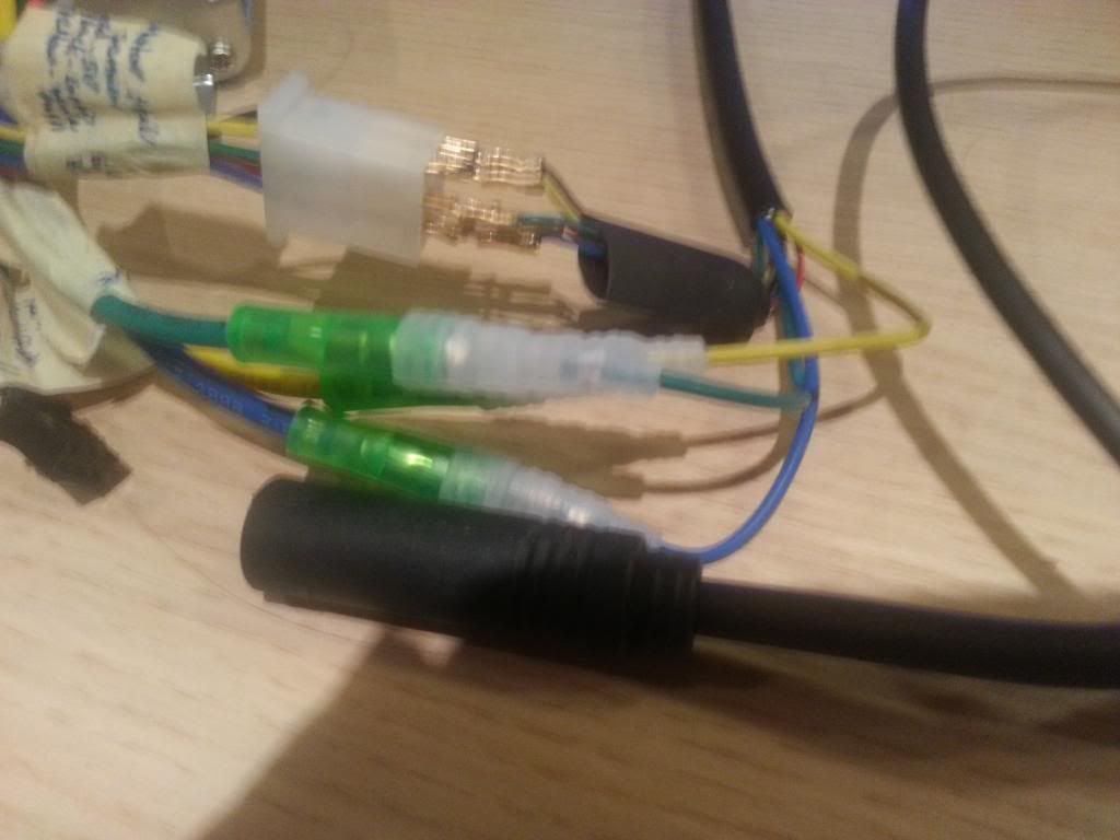
Having paired up all the bits received with CST and controller, am a bit flummuxed by the set of 5 pins soming out of the lead ... the 3 with connectors on I can marry up to the green, blue and yellow wires coming out of the controller with paired connector ends (green).

However I can;t work out what the very thin blue, green, black, red and yellow wires with spades on the ends housed in what looks like a large piece of black shrinkwrap are for :

20130203_040751[1].jpg

What's the story with these ?
 
D

Deleted member 4366

Guest
There's a white block on your controller with the corresponding wires on. For testing, you can poke the narrow spades in matching colour to colour. Check that none are touching each other before firing up the motor. To avoid touching, it helps to give them all the same orientation. There was a little plastic bag with the motor nuts, plastic caps, controller connector block and this connector block in it. Once you've made your box, you can thread these motor wires through and then clip the spades into their own connector block to match the one on the controller. You don't need the heat-shrink.

On your battery lead, where the heatshrink didn't cover the wire, just use a couple of turns of insulating tape around the wire.
 

banbury frank

Banned
Jan 13, 2011
1,565
5
WOW I have never seen anything as complicated our new CST kit is all on plugs that are waterproof and colour coded with room in the battery case that clamps to the seat post down tube for our new shrink battery pack controller and spare cable all you need is a spanner to tighten the wheel nuts

Allen key to attach the throttle and Philips screw driver to attach the display

No Soldering no heat shrink no Diagram Battery connection on Anderson connectors

There is a range off talk arms you may have to drill a 7 mm hole

Frank
 
Last edited:

banbury frank

Banned
Jan 13, 2011
1,565
5
Hi our New kit was designed with a Bike mechanic in mind these kit are for a bike shop to install on standard bikes The £995 +vat RRP

Starting price for rear motor 48 volt 10AH battery 15AH and 20AH upgrade Available The shop will receive a Trade Price

You will be able to buy from them or our website and fit yourselves or there will be a £200 / 300 + vat fitting Charge

Frank
 
D

Deleted member 4366

Guest
The kit from BMSBattery is the same. You can put the controller and battery in a seatpost bag. The connectors just clip together; bolt on the motor and torque arm; one screw for the throttle and away you go. The only extra thing is the battery to controller connection because you buy the battery seperate to the kit (more choices). Alex doesn't want his like this though. He wants a triangle mounted battery with remote switch, which brings a few more complications. Plus, he's never seen this sort of stuff before, so he doesn't know what's what. You'd have this kit installed in about 10 minutes.
 

103Alex1

Esteemed Pedelecer
Sep 29, 2012
2,228
67
Hi our New kit was designed with a Bike mechanic in mind these kit are for a bike shop to install on standard bikes The £995 +vat RRP

Starting price for rear motor 48 volt 10AH battery 15AH and 20AH upgrade Available The shop will receive a Trade Price

You will be able to buy from them or our website and fit yourselves or there will be a £200 / 300 + vat fitting Charge

Frank
I'll be happy to babysit a demonstrator for you and fit some kits to people's existing bikes - should have all the requisite skills by the time I finish this job lol. I think you supply a great kit, Frank and no supplier has taken so much time to discuss things with me in such depth or with such detailed technical knowledge - as you know I very nearly bought one but in the end the £500-£600+ price differential was one I simply can't fund (right now at least) and I needed to get something in the pipeline. Besides, my motor had already shipped... and crazy as it sounds the extra hole to be drilled in my Trek frame was one of the key factors which persuaded me to go ahead and fit the CST parts (it's not a kit as such with this option - you specify the components and then do the assembly yourself).

Looking objectively though, the way this is panning out I am learning so many new skills which buying a "sit while we fit" option would never have given me the opportunity to learn at a time when finally I have the time window to take the opportunity on that in my case at least am looking positively at the complexity, some of which is just me being demanding about quality upgrading. I also wanted to keep my cassette and 27-sp gearing so didn't go for the easy option of a Bafang kit. Not the easiest choice to cut your teeth on but I was fully prepared for that. However, for most people who aren't ready to take on the extra work and have the money I reckon your option can only be seen as an attractive one - Silent Wing Kube version in particular ;).
 
Last edited:

103Alex1

Esteemed Pedelecer
Sep 29, 2012
2,228
67
There's a white block on your controller with the corresponding wires on. For testing, you can poke the narrow spades in matching colour to colour. Check that none are touching each other before firing up the motor. To avoid touching, it helps to give them all the same orientation. There was a little plastic bag with the motor nuts, plastic caps, controller connector block and this connector block in it. Once you've made your box, you can thread these motor wires through and then clip the spades into their own connector block to match the one on the controller. You don't need the heat-shrink..
Like this ?


The block the pins are in is labelled Motor Hall Sensor on the BMS guidance sheet

I checked all the bits I received and the only unused connector left in there is this one :

20130205_015606[1].jpg

There are 5 very small pins in there along with a black terminal with 5 holes arranged in a horizontal row ... so I don't think this is the right connector. The white motor hall connector on the controller has 6 holes with female contacts arranged in 3 rows of 2. These ain't going to marry up :confused:.... so do I need to find a connector to take those pins off the motor lead and match the motor hall connector on the controller ?
 
D

Deleted member 4366

Guest

103Alex1

Esteemed Pedelecer
Sep 29, 2012
2,228
67
That's not the right one. I wish you'd said before: Then I could've put one in the box with the switch. I have a few spare because I wired my last three direct to the controller PCB wothout a connector. This isn't so good with the battery in a box because you have to drill a bigger hole for the motor connector. If you look at post#10 here, you can see what I mean:
http://www.pedelecs.co.uk/forum/electric-bicycles/13226-new-build-carrera-kracken-conversion.html
Ah - hadn't got round to looking at it until last night to be honest. I went to Maplins today again to try to get various things and asked if they had one but they didn't. If you have one to spare that would be appreciated - or else if there's somewhere in UK I can buy one from on mail order I can do that if I know what to buy.

It looks like it's going to be several weeks before the box is built and installed anyway (the Speedict thing isn't resolved yet and I may yet wire in a basic 3-speed system as an alternative in case it isn't compatible with my phone as I can't afford to change my phone to match the Speedict !). Without everything being clear yet the box is going to have to be shelved for now. So a while yet before I need to make final decisions on the permanent controller wiring.

That controller box looks neat - much nicer. I guess by using Speedict you managed to get rid of most of the wires coming out of it ?

I was hoping to test the motor today, having gone up to the engineering firm to collect my drilled torque arm they have drilled the wrong size hole which is too big and matches the pivot hole instead of the fixing hole. I may be able to find a temporary bolt but they have basically b*ggered it as it won;t work with my rack so probs have to buy another adjustable one now. I'm pretty speechless .... and just a little worn out with it all now lol. Time to take a step back and try to get everything in persepctive.

I can't get into the mail box at the moment as she who must be obeyed has gone off to work with the key by accident :)rolleyes:) but later this evening hopefully be able to check out for the switch to brighten up a frustrating day :)
 

Old_Dave

Esteemed Pedelecer
Sep 15, 2012
1,211
2
Dumfries & Galloway
Over size bolt.. Turn down to create a plain shoulder, turn the rest down to correct size then thread it..

Or just make a sleeve to reduce the hole size.

You always wanted a small lathe :p


Sent from my iPhone using Tapatalk
 
Last edited:

103Alex1

Esteemed Pedelecer
Sep 29, 2012
2,228
67
Over size bolt.. Turn down to create a plain shoulder, turn the rest down to correct size then thread it..

Or just make a sleeve to reduce the hole size.

You always wanted a small lathe


Sent from my iPhone using Tapatalk
Gone one better ... attacked it with a hammer and my bastard file ... have now got the desired 'kink' in it which they didn't do as asked either ... and as fortune would have it this pushed their hole off centre, so what remains to receive the original bolt diameter to match the rack mount and the frame hole is exactly the right size :D ... even better the fractions of a mm shaved off the edge to let the axle nut screw on mean that the nut is so tight against the retaining plate there's no way the plate can slip out of alignment. Miracle.

Must learn not to be frustrated too early ;) .. it's looking pretty good actually now after receiving a good bashing :p

20130205_181224[1].jpg20130205_181243[1].jpg

Will replace the bolt with a shorter one I have (nut on the back of the frame hole) and refit the rack over the top so the bolt will not be in the way of the brake discs but other than that I think it's a "job done" on that one. Right, off to the gym now (feeling ready for it after the hammering & filing lol) to get rid of the rest of the day's irritations.

Be good to test that motor pretty soon now :D
 
Last edited:

Old_Dave

Esteemed Pedelecer
Sep 15, 2012
1,211
2
Dumfries & Galloway
Well done you... .:D

A washer on the bolt would be a nice touch (maybe a stainless one)


Sent from my iPhone using Tapatalk
 
D

Deleted member 4366

Guest
I'll put one of those connectors aside for now, but I won't send it just yet in case you need something else - like a torque arm. I think I've got a BMSBattery one somewhere, which you can have for £7.50 if you want it, which is about what I paid for it. Didn't you get a pair of them from BMSBattery?

I just bought a set of cobalt drills in case I have to drill one again.
 

103Alex1

Esteemed Pedelecer
Sep 29, 2012
2,228
67
Well done you... .:D

A washer on the bolt would be a nice touch (maybe a stainless one)


Sent from my iPhone using Tapatalk
Agreed - picked a few up earlier at the machining place too ... will add to finish off. Love it when a plan comes together ... and looks really neat, will just disappear once the brake disc is on the motor and the rack is remounted, and as it's basically fitted to measure it's as solid as a rock :cool:. Was worth it in the end. Thanks Old_Dave & d8veh for the guidance. One day I'll have my own tools to drill my own holes the right size lol ... but till then .... :)
 

103Alex1

Esteemed Pedelecer
Sep 29, 2012
2,228
67
I'll put one of those connectors aside for now, but I won't send it just yet in case you need something else - like a torque arm. I think I've got a BMSBattery one somewhere, which you can have for £7.50 if you want it, which is about what I paid for it. Didn't you get a pair of them from BMSBattery?

I just bought a set of cobalt drills in case I have to drill one again.
Thanks d8veh. I think I'm ready to test the motor at least on the upturned dropouts of the bike (I guess this is how you do it if the wheel has no tyres yet ?).

Just to be absolutely sure, am I good to go testing the motor with the Hall sensor pins popped in that connector and not touching like you said before ? Is there any particular sequence I need to connect things up in so as not to make a mistake ?

PS - The switch arrived today - I finally just got into the mail box and it was there :cool:. I am still deliberating on the toggle switch :)rolleyes: - decisiveness not my forte on fittings lol) after finding a DPDT one I liked this afternoon and the Maplins guy saying I needed to get a SPDT one if there were only 2 pins being connected up to the switch but will browse a bit more on-line and try to get one with 2 pins ordered in tonight.

I'm presuming I can add that in later and just test with the wires I've got to hand now ?
 
Last edited:
D

Deleted member 4366

Guest
Looks like you're ready to go. Just make sure that those exposed pins don't touch.
 
D

Deleted member 4366

Guest
Alex, your message box is full. You need to empty it to make space to receive further messages.
 

103Alex1

Esteemed Pedelecer
Sep 29, 2012
2,228
67
Oops ... space made now.