Cyclamatic: The Beastamatic is dead! Long live the Beastamatic

  • Thread starter Deleted member 4366
  • Start date

evendine

Pedelecer
Jan 8, 2012
126
-1
An unexpected new result from further testing:

If you rotate the pedals backwards a bit and then give the wheel a good spin forwards; the motor works every time on the throttle. Very strangely, if you spin the wheel up using the pedals and then pedal backwards the motor kicks in running forwards normally in assist mode, as it were! :D

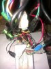
Can't help thinking that the pedal hall sensor is reverse wired, somehow! (Have checked the magnet ring and the arrows look right). The white wire from the throttle is connected to the red wire of the pedal hall sensor, btw...
 

evendine

Pedelecer
Jan 8, 2012
126
-1
Re: hall sensor test questions:

Black - red = 5v constant
Black - Yellow + wheel rotation = 5v (no change to 0v during rotation)
Black - Green + wheel rotation = 5v (no change to 0v during rotation)
Black - Blue + wheel rotation = 5v (no change to 0v during rotation)
 
D

Deleted member 4366

Guest
The magnet disc is back to front. Take it off and flip it.

The Cyclamatic pedal sensor works backwards when compared with standard ones, so maybe sommeone bought a new one and didn't realise.

That potentiometer must be on the speed limit wire in attemt to change it, but I'msure that can't work.

Can you post a picture of the controller and wires? It wouldn't surprise me if the controller was changed, which would account for the backwards pedal sensor.
 
D

Deleted member 4366

Guest
Can you check again the black and red hall sensor wires takking notice of polarity - so put your black probe on the black wire and red on red, and then check whether it's + or -5v. It could be that the controller is running sensorless because it doesn't get a hall signal. Hence the bad starting. I need to see a photo of it.
 
D

Deleted member 4366

Guest
Another thought: Do the colours match on both sides of the hall connector, i.e. black to black and red to red.
 

evendine

Pedelecer
Jan 8, 2012
126
-1
Here's a pic which shows the pedal sensor lead at the top right (red black, green) and the throttle lead bottom right with the blue tape. As you can see, the white throttle wire connects directly to the red pedal sensor wire. The mini-pot wires both go directly into the controller.
 

Attachments

evendine

Pedelecer
Jan 8, 2012
126
-1
Yep - hall sensor colours match and +5v rail is correct...

Have just flipped the pedal magnet and hey-presto, we now have pedal assist and throttle power :D

Startup on both seems off, though - seems as though the throttle / pedal assist 'on set-point' may be wrong. With the throttle, it's as though it does nothing until you have it half open. With pedal assist, you have to pedal quite hard for it to cut in. Wondering if the pot is related to that?

Still need some forward motion on rear-wheel to get throttle power going...
 

evendine

Pedelecer
Jan 8, 2012
126
-1
Have tweaked the pot and it seems to effect the 'cut-in' setting on the throttle - will have to take a spin round the garden to see how it works in pedal assist mode...
 

evendine

Pedelecer
Jan 8, 2012
126
-1
Yep - 12A standard one, i think...

Just tried it out round the garden - pedal assist and throttle both work, but still intermittent. Seems ok until i use the brakes. Starting to wonder if the malfunctioning rear-brake sensor is intermittent? Motor is way noisier than either of the other two i've had.

Any thoughts on the wiring loom?
 

evendine

Pedelecer
Jan 8, 2012
126
-1
D

Deleted member 4366

Guest
You can disconnect the brake switch connector to test if it's having a detrimental effect.

The noise could be a couple of teeth stripped off a gear, but I would explore other possibilities first.
 

evendine

Pedelecer
Jan 8, 2012
126
-1
Tried disconnecting the problem brake switch - no effect.
Experimented combinations of wheel hall sensor wires. None are better than the original.

Have been wondering if the issue is one of current delivery from the battery. This might make sense as start-up = max current and once the back wheel's moving, it works ok. The main batt connectors had been (very roughly) soldered at some point, so cleaned them back to the metal. Just thinking it's possible that the wires on the back of the connector may have a poor connection, which is limiting current availability.
 

evendine

Pedelecer
Jan 8, 2012
126
-1
I have one on my other bike, but it doesn't have the connector between the controller and wheel, unfortunately. Could park them close together and replug the loom motor / sensor connectors, I suppose? Any possibility of frying the good controller, do you think?

Further testing on the motor hall sensors' volts revealed the following: Yellow lead voltage is flat 0v, whichever direction you turn the wheel. Blue shows around 0.2v for part of the rotation and 0v otherwise, but only when the wheel is turned backwards. Green does what I would expect - alternating between 0 and 5v regularly, but again only when wheel's turned backwards. For all colours, rotating forwards gives flat 0v.

This may explain why you have to rotate the wheel backwards a little way to get the motor going. Hard to understand why everything to do with hall sensors seems to be backwards on this bike! :confused:
 
Last edited:
D

Deleted member 4366

Guest
That just doesn't sound right. If the halls were faulty, it wouldn't run at all. Maybe it would run rough is one was down. Really, you need to check with an independent 5v supply like a phone charger if you can. That will eiminate any problem with the controller, or pull the hall pins out of the connector -just leave the black and the red in to power them.
 

evendine

Pedelecer
Jan 8, 2012
126
-1
Following your advice, dug out a phone charger and knocked a little test rig up consisting of some temp female connectors (computer psu connectors fit) and a 10k pull-up resistor connected between +5v and the probe. Ran the test completely disconnected from the controller, as you suggested.

Results were as follows:

When the wheel was rotated backwards (against direction of drive) - proper alternation of voltage between +5v and 0v on all three sensors. When rotated forwards (towards direction of drive), no change of voltage (stayed at 0v if originally 0v and 5v if 5v before turning).

Can only put the couple of spurious previous results down to poor connection through the back of connector, as the controller was plugged in.

On the positive side, it seems the sensors are ok, but how on earth can they only be working when the wheel is rotating backwards!? :confused::confused: I can't explain it!
 
Last edited:
D

Deleted member 4366

Guest
It's obvious. There's a clutch in the motor. It only turns when you rotate the wheel backwards!

At least now you know that you can use your other conroller without damaging it.
 

evendine

Pedelecer
Jan 8, 2012
126
-1
Ahhh! - yep - mechanics never was my strong point! :p:D

Safe to only plug the motor connections in from the other bike do you think? Should help narrow down the issues...