

Cyclematic powerplus
- Thread starter gazza19
- Start date
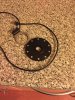
Would this do to extend the battery connections to the controller connections decided to put it in a bag as scared of breaking wires trying to get it inside the space obviously I’d get the male part too https://www.switchelectronics.co.uk/prewired-female-xt60-connector-10cm?gclid=Cj0KCQiA1KiBBhCcARIsAPWqoSohUM8PBXZ_DIrzy5dsqAlD9WhmIkYbmSNeHb_9WhQ6OfbfKu3HxroaAt3EEALw_wcB
If you don't want to solder or cut wires, that won't work.Would this do to extend the battery connections to the controller connections decided to put it in a bag as scared of breaking wires trying to get it inside the space obviously I’d get the male part too https://www.switchelectronics.co.uk/prewired-female-xt60-connector-10cm?gclid=Cj0KCQiA1KiBBhCcARIsAPWqoSohUM8PBXZ_DIrzy5dsqAlD9WhmIkYbmSNeHb_9WhQ6OfbfKu3HxroaAt3EEALw_wcB
Do what I said further up. Cut about 6" of innertube; slide it over the wires and connectors; put a tight cable tie around the top end and a looser one at the bottom; cable tie the whole lot, top and bottom, to the frame.

XT60 are ideal but you need to be able to solder, I use them or the 90's. Occasionally you get a bad contact because the M/F pins become slack, it is easily remedied by using a panel pin or similar up the centre of the male pin by gently pushing the four segments slightly apart.
Hi im wondering if anyone can help me please. I have a cyclematic powerplus 24v 250watt motor bike and ive just fitted a kt lcd3 does anyone know what the p and c parameters are for this bike please also when i press the throttle sometimes it kicks in and other times it does not any help would be greatly appreciated as im finding it hard to do. Many thanks for any help givenXT60 are ideal but you need to be able to solder, I use them or the 90's. Occasionally you get a bad contact because the M/F pins become slack, it is easily remedied by using a panel pin or similar up the centre of the male pin by gently pushing the four segments slightly apart.
P1 start with 84 set the speed in the previous menu to 25km/h and go for a ride with a GPS readout to see how far out the lcd reading is compared to GPS. If LCD reading is lower then set P1 one digit higher and test again, repeat until they are very close. If the opposite and lcd reads high then go down a digit at a time.
P2 depends on speed sensor magnets usually 1 or 6 is the answer but if you had two motor speed magnets then set it to 2.
P3/1 current control or 0 if you prefer speed control.
P4 throttle use 0 always active illegal if post 2016 or 1 active/pedal first.
P5 10.
C1 PAS we need to know which PAS sensor you are using.
C2 0 is default motor should sound very quiet and run smoothly.
C3 Pas level 0 - 5 will auto register to the selected level every time you switch on , so if you select 3 PAS level 3 will be registered every time you switch on or 8 will use the last registered PAS level you used.
C4 is throttle speed setting. 0 no speed set, 1 walk assist or 2 spd lmt specified.
C5 current delivery 10 is max current other values reduce the max current.
C6 lcd display light brightness.
C7 Cruise leav eas 0/off.
C8 0/off it is for motor temp, there is no sensor for this.
C9 Password setting 0 off or 1 if you want ot set a numeral P/W every time you switch on.
C10 System reset. N or Y.
C11 0 LCD 3comms display used. 1 for lcd 1 or 2.
C12 controller lvc voltage leave as 4,5 or 6. Your battery BMS lvc will likely be higer any way.
C13 ABS regen leave as 0.
C14 PAS signal strength 1 weak - 3 strong.
If really lucky you may have L setting as well.
Is so leave as L1 0, L2 0, L3 1. L4 is lcd shutdown time in mins.
You probably have the wrong connection sequence. The wires don't necessarily go colour to colour when you fit a different controller. You need to go through all combinations of three phase wires and 3 hall wires, which makes 36 possibilities of which three will work correctly and three will turn the motor backwards.. there was a recent thread where a guy had the same as you. I think he only had to swap the phase wires, which means only three possible combinations tp try.Hi im wondering if anyone can help me please. I have a cyclematic powerplus 24v 250watt motor bike and ive just fitted a kt lcd3 does anyone know what the p and c parameters are for this bike please also when i press the throttle sometimes it kicks in and other times it does not any help would be greatly appreciated as im finding it hard to do. Many thanks for any help given
Hi neath this is the pas sensor I got with the kit it is a ten magnet one thank you for all the info you sentP1 start with 84 set the speed in the previous menu to 25km/h and go for a ride with a GPS readout to see how far out the lcd reading is compared to GPS. If LCD reading is lower then set P1 one digit higher and test again, repeat until they are very close. If the opposite and lcd reads high then go down a digit at a time.
P2 depends on speed sensor magnets usually 1 or 6 is the answer but if you had two motor speed magnets then set it to 2.
P3/1 current control or 0 if you prefer speed control.
P4 throttle use 0 always active illegal if post 2016 or 1 active/pedal first.
P5 10.
C1 PAS we need to know which PAS sensor you are using.
C2 0 is default motor should sound very quiet and run smoothly.
C3 Pas level 0 - 5 will auto register to the selected level every time you switch on , so if you select 3 PAS level 3 will be registered every time you switch on or 8 will use the last registered PAS level you used.
C4 is throttle speed setting. 0 no speed set, 1 walk assist or 2 spd lmt specified.
C5 current delivery 10 is max current other values reduce the max current.
C6 lcd display light brightness.
C7 Cruise leav eas 0/off.
C8 0/off it is for motor temp, there is no sensor for this.
C9 Password setting 0 off or 1 if you want ot set a numeral P/W every time you switch on.
C10 System reset. N or Y.
C11 0 LCD 3comms display used. 1 for lcd 1 or 2.
C12 controller lvc voltage leave as 4,5 or 6. Your battery BMS lvc will likely be higer any way.
C13 ABS regen leave as 0.
C14 PAS signal strength 1 weak - 3 strong.
If really lucky you may have L setting as well.
Is so leave as L1 0, L2 0, L3 1. L4 is lcd shutdown time in mins.
Attachments
-
 1.4 MB Views: 5
C1/2 should do the trick, before you fit it plug it in and wave the disc past the sensor to make sure the hub turns the right way. Other wise you have to take the crank off again to flip the magnet disc.
But as vfr has mentioned the phase /hall combos don't always work colour to colour but doing so colour to colour is a starting point, if one thinks the hub doesn't sound right then try the other options in C2 but don't force the issue if the motor becomes noisy. C2 will change the combo's so worth a try if not happy with the running after that one has to go down the manual route to which we can supply a chart to follow with switching the 36 combo's.
But as vfr has mentioned the phase /hall combos don't always work colour to colour but doing so colour to colour is a starting point, if one thinks the hub doesn't sound right then try the other options in C2 but don't force the issue if the motor becomes noisy. C2 will change the combo's so worth a try if not happy with the running after that one has to go down the manual route to which we can supply a chart to follow with switching the 36 combo's.
Last edited:
thank you neath for replying il set it all up in next couple of days and hopefully it all works ok just hope the throttle works properly tooC1/2 should do the trick, before you fit it plug it in and wave the disc past the sensor to make sure the hub turns the right way. Other wise you have to take the crank off again to flip the magnet disc.
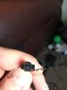
Here are the new and old pas sensors on the new one its all male connectors on the controller side its two male and a separate female would I be able to block connect the two male and the female together as i haven’t got the female new parts for them it’s for a coyote connect that I’m hoping to use as a spare bikethank you neath for replying il set it all up in next couple of days and hopefully it all works ok just hope the throttle works properly too
Attachments
-
 843.4 KB Views: 2
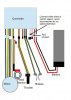
All the common pedal sensors have three wires. The third wire on your bike is a red one from the pedal sensor that's connected to a white one in the throttle cable. The Cyclamatic wiring is unusual in that instead of getting the 5v direct from the controller, it takes a branch off the throttle's 5v. That's so that you can use the red switch on the throttle to switch it off.
You can use your Cyclamatic PAS but you have to flip the magnet disc to stop it from only working when you pedal backwards.
When you use a new controller with LCD and you keep the Cyclamatic throttle, you only connect the red, yellow and black wires to the 3 throttle wires on the new controller.
You can use your Cyclamatic PAS but you have to flip the magnet disc to stop it from only working when you pedal backwards.
When you use a new controller with LCD and you keep the Cyclamatic throttle, you only connect the red, yellow and black wires to the 3 throttle wires on the new controller.
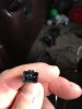
thank you pal sorry i didnt explain it right the pedal assist in the pic is for a coyotte connect electric bike im hoping to use a spare bike thats why i was asking if i can terminal block itAll the common pedal sensors have three wires. The third wire on your bike is a red one from the pedal sensor that's connected to a white one in the throttle cable. The Cyclamatic wiring is unusual in that instead of getting the 5v direct from the controller, it takes a branch off the throttle's 5v. That's so that you can use the red switch on the throttle to switch it off.
You can use your Cyclamatic PAS but you have to flip the magnet disc to stop it from only working when you pedal backwards.
When you use a new controller with LCD and you keep the Cyclamatic throttle, you only connect the red, yellow and black wires to the 3 throttle wires on the new controller.
View attachment 40896
There's no power in those wires, so in principle yes, but copper corrodes in air, which would give problems in the long-term. Maybe add some silicone grease or vaseline to keep out the air.thank you pal sorry i didnt explain it right the pedal assist in the pic is for a coyotte connect electric bike im hoping to use a spare bike thats why i was asking if i can terminal block it
thank you just another question what ampage ones would you use as the wire is only thin isnt itThere's no power in those wires, so in principle yes, but copper corrodes in air, which would give problems in the long-term. Maybe add some silicone grease or vaseline to keep out the air.
As small as you like. There are virtually no amps - maybe 5mA or less.thank you just another question what ampage ones would you use as the wire is only thin isnt it
thank you vfr400As small as you like. There are virtually no amps - maybe 5mA or less.
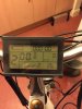
Does anyone know why i am getting a sour 2 on my my lcd3 please and how to rectify it also I’m getting an end on the motor partthank you vfr400
Attachments
-
 910.3 KB Views: 5
There is no battery metre capacity shown, it appears empty ?
Never seen that meaning displayed before.
Can you explain the very last bit of the sentence as I can't understand what it means.
Never seen that meaning displayed before.
Can you explain the very last bit of the sentence as I can't understand what it means.
it was showing before i set the p and c parameters up when i press the up and down buttons together is shows end where the motor reading normally is there a wat to set it back to factory settings and try againThere is no battery metre capacity shown, it appears empty ?
Never seen that meaning displayed before.
Can you explain the very last bit of the sentence as I can't understand what it means.
Related Articles
-
 MTF Enterprises announces acquisition of EMU Electric Bikes
- Started by: Pedelecs
-
 Wisper 806T folding bike wins Which? ‘Best Buy’
- Started by: Pedelecs
-
 Sustrans calls for protected cycle lanes
- Started by: Pedelecs
-
 Amazon launch their first UK e-cargo micromobility hub
- Started by: Pedelecs
