ERider moped Help

billyboya

Esteemed Pedelecer
Aug 10, 2016
974
88
72
uk
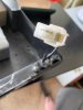
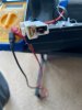
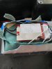
I concur with Pete, from what I see the 2nd pic is a DC jack charge point 5.5mm x 2.1mm or 2.5mm. The pin in the middle is V+ contact and the metal barrel inside is the V-, in side the Black wire you talk there are two thinner wires (one Red/one Black) the outer is just a pvc sheath. It isn't man enough for discharge and will be capable of about 4-7a max.

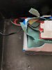
The kettle plug type is the discharge unless you aren't showing everything one has to use logic. The bike will be discharging some 20a plus I would say.

It's likely you are bypassing the BMS if the lipo/battery has one and reverse charging. You need to trace that jack plug (pic # 2) and find out exactly where the end goes, instead of guessing and taking chances.

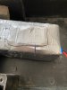
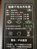
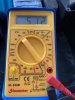
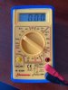
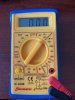
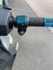
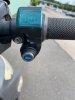
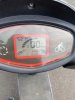
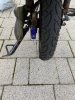
Hi yes just got home after dam walking moped back, I didn't go very far so not too far to push it home. its defo a wiring fault somewhere or loose wire. as when I was on way home. it kept like cutting out. go 2 yards stop etc. then I noticed on dash nothing at all. I have now just tested battery had to open up the case as it don't seem to test on 2 of those 3 pins, maybe that's the cause don't know. Hi yes I do apologies to wheeliepete there is 2 wires on that black lead. so are you saying I should be charging battery with a charger plugged into that DC jack charge point, as this seller told me that at 1st he was told the other charger he was using was for SLA batteries not Lithium, so he then bought this charger which has a 3 pin plug at end. so are you now saying I will need a charger what plugs into that DC jack one. to now charge up battery if so what one is it then. but the 3 pin is just what you plug in lead on moped battery compartment. so the charger I have uploaded images isn't the right one as it charges up battery ok. I do think there is maybe a BMS under all that grey tape over battery as you can see by image I have marked a black line around it what feels like a meter under grey tape. so this 3 pin end charger I have now what is that for then as its red when charging and green when batt is fully charged. I have also taking a picture of that key slot on right handle bar with some sort of meter above it. but I only have 1 key for bike. and it don't fit that. also at rear of back wheel I also saw this blue plastic tab thing lifted it open and there is another key slot but again no key I have a feeling that maybe an alarm. I will cut around that grey tape late on battery to see if that is the bms
 

Attachments

billyboya

Esteemed Pedelecer
Aug 10, 2016
974
88
72
uk
Your picturein post#1 clearly shows that the kettle socket is the discharge socket to power the bike and the 5.5mm jack socket is the charge socket. You should only charge through the 5.5mm one if you want to avoid an explosion and fire.

Whatever connector you have on the charger, you must change it to a 5.5mm jack. Bear in mind that the colours of charger wires are often the wrong way round, so always test with a meter after fitting a new connector and beefore inserting into the battery, otherwise you get a big bang.

Dam the bloody seller was even charging it from that 3 pin kettle plug on charger. can you not get an adapter for that 3pin to a dc jack then or am I going to have to buy now another charger with a dc jack on end. so I take it the charger I have is fine but need a DC socket at end instead of that 3 pin kettle one or if not how many wires in that to solder to a dc jack one as I have soldering iron. as you can see it is the bms then under battery so is there a adapter what can plug into that 3pin plug and has a dc socket other end please. also I am going to have to take moped to a place where they check wiring

so is this charger I have ok now once I change the 3 pin kettle plug to a DC jack one can someone here help me to get right dc jack plug and is it 2 wires as on charger I know on the DC jack plug negative goes to the outer casing and positive red wire goes to inner according to my charger symbols. is it a male or female dc jack plug I think its prob female
 

Attachments

Last edited:

vfr400

Esteemed Pedelecer
Jun 12, 2011
9,822
3,986
Basildon
Dam the bloody seller was even charging it from that 3 pin kettle plug on charger.
That's probably the reason why the battery is not performing very well. Before going any further, you should check the battery and the charger.

Looking at the picture of the BMS, I can see P- on the left side where the thick black wires is fixed. You need to find B-, which is where the thick black wire from the cell-pack is attached to the BMS. That looks like it at the bottom right, but check the writing on the BMS. Using the B- as the ground for your black probe, check the voltage on each of the pins on the back of the multi-pin connector on the right side with your red probe. Be very careful not to let your probe touch two pins at the same time. Write down the voltage on each pin and post them here. Also, measure the voltage between the B- and anywhere where you can access the red wire or a pin attached to it.

After that, switch on the charger and measure the voltage between the outer two pins. The middle one isn't used for anything.
 

billyboya

Esteemed Pedelecer
Aug 10, 2016
974
88
72
uk
That's probably the reason why the battery is not performing very well. Before going any further, you should check the battery and the charger.

Looking at the picture of the BMS, I can see P- on the left side where the thick black wires is fixed. You need to find B-, which is where the thick black wire from the cell-pack is attached to the BMS. That looks like it at the bottom right, but check the writing on the BMS. Using the B- as the ground for your black probe, check the voltage on each of the pins on the back of the multi-pin connector on the right side with your red probe. Be very careful not to let your probe touch two pins at the same time. Write down the voltage on each pin and post them here. Also, measure the voltage between the B- and anywhere where you can access the red wire or a pin attached to it.

After that, switch on the charger and measure the voltage between the outer two pins. The middle one isn't used for anything.
Hi I really appreciate your help and also others here too. I’ve learnt loads. I will tear a bit more to show the bms connections you asked. You say switch on the charger and measure voltage between the 2 outta pins I take it you mean that kettle plug on charger . Can you just tell me what setting I put multimeter on to check that. Also what type of dc Jack do I fix to charger instead of that 3 pin plug. I know the neg is to go on outside pin on Jack plug and pos to the inner pin. And is my charger ok then, All I need to know then is which is neg and pos on charger wires

also what setting do I put multimeter on when checking pins electrics is my hobby but I’m not 100% at it yet but love to learn stuff
 

Attachments

Last edited:

wheeliepete

Esteemed Pedelecer
Feb 28, 2016
2,047
755
60
Devon
Those jack plugs are very fiddily to solder esp. if the wire is quite thick like the wire on your charger. An easier option would be to leave the charger alone and connect a kettle socket to the wires on the battery. If you have some longer wire to hand you could put the socket under the seat. It would save you needing to remove the floor of the bike every time you want to charge the battery. Take care not to short the wires on the battery, cut, connect and insulate them one at a time and stagger the join. Cut one of these to length.
 

billyboya

Esteemed Pedelecer
Aug 10, 2016
974
88
72
uk
Those jack plugs are very fiddily to solder esp. if the wire is quite thick like the wire on your charger. An easier option would be to leave the charger alone and connect a kettle socket to the wires on the battery. If you have some longer wire to hand you could put the socket under the seat. It would save you needing to remove the floor of the bike every time you want to charge the battery. Take care not to short the wires on the battery, cut, connect and insulate them one at a time and stagger the join. Cut one of these to length.
Hi I thought the 3 pin socket was the discharge socket but now you say don’t put a DC Jack plug at end of charger they can’t be that hard to solder just 2 wires to the Jack plug. I don’t think the 2 wires on the charger are that thick. Also I live in a 1st story flat and have a shed on ground floor for moped so have to take battery up to flat to be charged can’t do it down stairs. So is my charger ok then once I solder a dc Jack plug
 

Nealh

Esteemed Pedelecer
Aug 7, 2014
20,139
8,232
60
West Sx RH
For BMS pins measuring each one against B- use the 20v setting it will give a more accurate reading like 3.86 as an an example. If you use the 200v setting it will simply read 3.9v as it will round up.
For the charger pins you will use 200v setting.
 

vfr400

Esteemed Pedelecer
Jun 12, 2011
9,822
3,986
Basildon
Hi I really appreciate your help and also others here too. I’ve learnt loads. I will tear a bit more to show the bms connections you asked. You say switch on the charger and measure voltage between the 2 outta pins I take it you mean that kettle plug on charger . Can you just tell me what setting I put multimeter on to check that. Also what type of dc Jack do I fix to charger instead of that 3 pin plug. I know the neg is to go on outside pin on Jack plug and pos to the inner pin. And is my charger ok then, All I need to know then is which is neg and pos on charger wires

also what setting do I put multimeter on when checking pins electrics is my hobby but I’m not 100% at it yet but love to learn stuff
You don't need to tear anything. You probe those pins on the back of the connector that you can see in the photo. I'd use the 200v DC setting for everything. That will be ccurate enough and saves messing about.

You need the matching jack that fits the socket, which is a standard 5.5mm jack that you can find on Ebay.
 

billyboya

Esteemed Pedelecer
Aug 10, 2016
974
88
72
uk
For BMS pins measuring each one against B- use the 20v setting it will give a more accurate reading like 3.86 as an an example. If you use the 200v setting it will simply read 3.9v as it will round up.
For the charger pins you will use 200v setting.
its so awkward to measure BMS pins using B- and I set it to 20v setting as in image below I have now just tried 2 pins and all they read is 1 . but if I turn multimeter dial to the V 200 mark and then check pins

1st = 52V 2nd= 48V 3rd= 44V 4th=40V 5th=36V 6th=32V 7th=28V 8th=24V 9th=20V 10th=16V 11th=12V
12th=8V 13th=4V and last 14th had no reading

it was so dam hard to test those pins as cant hardly see them had to wear a pair of magnifying glasses. trouble is the prob seems bigger than the pins so was very careful
 

Attachments

Last edited:

billyboya

Esteemed Pedelecer
Aug 10, 2016
974
88
72
uk
You don't need to tear anything. You probe those pins on the back of the connector that you can see in the photo. I'd use the 200v DC setting for everything. That will be ccurate enough and saves messing about.

You need the matching jack that fits the socket, which is a standard 5.5mm jack that you can find on Ebay.

so these in ebay link are what I need to fit the socket and how do I tell on charger which is neg wire and pos wire or will they be red black when I strip outer case off if so then I know red is pos and is this in image the correct dial on meter to test

Yes I think that dial on meter is right setting to test charger lead I just tried and it says 118.8V
 

Attachments

vfr400

Esteemed Pedelecer
Jun 12, 2011
9,822
3,986
Basildon
That's the setting for AC volts. You measure the charger with the same 200v setting as you used to measure the battery, which is the 200v at the 11 o'clock position. We need the decimal from this measurement.

The battery measurements show that it's nicely balanced. The 200v scale should give a decimal, like 4.1, 8.2, etc. Did you leave that off when you wrote down the numbers, because it's needed.

The reason the 20v scale won't work is that it only goes up to 20v, so can't show anything higher, and most of those pins are above that.
 

Nealh

Esteemed Pedelecer
Aug 7, 2014
20,139
8,232
60
West Sx RH
its so awkward to measure BMS pins using B- and I set it to 20v setting as in image below I have now just tried 2 pins and all they read is 1 . but if I turn multimeter dial to the V 200 mark and then check pins

1st = 52V 2nd= 48V 3rd= 44V 4th=40V 5th=36V 6th=32V 7th=28V 8th=24V 9th=20V 10th=16V 11th=12V
12th=8V 13th=4V and last 14th had no reading

it was so dam hard to test those pins as cant hardly see them had to wear a pair of magnifying glasses. trouble is the prob seems bigger than the pins so was very careful
Not correct, wrong scale.
One can use vfr's way or if you want three figure readings in the 3 or 4.xx way follow the route below.

One can also measure differently so that yo get 13 individual readings in the single range of up to 4.20v each which will give a better accurate reading of each group using the 20v setting.
You will need a couple of needles to help and ideally insulate all but the two ends so as not to cause a short (once done bend them slightly).

Cell group #1 (Cg#1) On the White multi wire sense connector disconnected from the BMS, place one needle in the Black pin out and the other in the first White pin out. Place probes with Red probe always on the second needle away from Black wire on the ends and see a single number voltage cell count in three figures like 3.98v or 4.05v etc ,etc.

Cg#2 , move the 2nd needle along one to the next White wire pin out, then move the other needle in to the position it vacated. Again probe the needles to get the single three figure voltage reading.

Cg#3, repeat as for Cg#2 until you have done this 13 times to get 13 single cell voltage readings, the last reading the needle will end up in the Red pin out and in the one proceeding it.

Each White wire x 12 are cell group positives when using the main B- direct off the battery pack and the last thin Red wire is positive for the cell group #13.

Taking readings in the way I mention by starting with the B0/B1 off the sense wire block each White pin out proceeding the next one acts as the negative as the pins are moved along in pairs as I have mentioned, the pin outs equate to 13 paired moves for the 13 cell voltage readings.
 
Last edited:

Nealh

Esteemed Pedelecer
Aug 7, 2014
20,139
8,232
60
West Sx RH
its so awkward to measure BMS pins using B- and I set it to 20v setting as in image below I have now just tried 2 pins and all they read is 1 . but if I turn multimeter dial to the V 200 mark and then check pins

1st = 52V 2nd= 48V 3rd= 44V 4th=40V 5th=36V 6th=32V 7th=28V 8th=24V 9th=20V 10th=16V 11th=12V
12th=8V 13th=4V and last 14th had no reading

it was so dam hard to test those pins as cant hardly see them had to wear a pair of magnifying glasses. trouble is the prob seems bigger than the pins so was very careful
Move the dial in the pic one click to the right to 200v and not all the way to 200v AC past the 12 o'clock position.
 

billyboya

Esteemed Pedelecer
Aug 10, 2016
974
88
72
uk
That's the setting for AC volts. You measure the charger with the same 200v setting as you used to measure the battery, which is the 200v at the 11 o'clock position. We need the decimal from this measurement.

The battery measurements show that it's nicely balanced. The 200v scale should give a decimal, like 4.1, 8.2, etc. Did you leave that off when you wrote down the numbers, because it's needed.

The reason the 20v scale won't work is that it only goes up to 20v, so can't show anything higher, and most of those pins are above that.

Hi I am very grateful for everyones help here its most appreciated believe me I have learnt loads so far. ok I have now tested all 14 pins again and its this is starting from 1st pin. 14th pin there is no reading ok 52.1 48.1 44.1 40.0 36.0 32.0 28.0 24.0 20.0 16.0 12.0 8.0 4.0 thats 13 pins and 14th dont read anything

ok now again tested charger lead on the on the 11 0clock setting and it says 54.1Volts
 

billyboya

Esteemed Pedelecer
Aug 10, 2016
974
88
72
uk
Not correct, wrong scale.
One can use vfr's way or if you want three figure readings in the 3 or 4.xx way follow the route below.

One can also measure differently so that yo get 13 individual readings in the single range of up to 4.20v each which will give a better accurate reading of each group using the 20v setting.
You will need a couple of needles to help and ideally insulate all but the two ends so as not to cause a short (once done bend them slightly).

Cell group #1 (Cg#1) On the White multi wire sense connector disconnected from the BMS, place one needle in the Black pin out and the other in the first White pin out. Place probes with Red probe always on the second needle away from Black wire on the ends and see a single number voltage cell count in three figures like 3.98v or 4.05v etc ,etc.

Cg#2 , move the 2nd needle along one to the next White wire pin out, then move the other needle in to the position it vacated. Again probe the needles to get the single three figure voltage reading.

Cg#3, repeat as for Cg#2 until you have done this 13 times to get 13 single cell voltage readings, the last reading the needle will end up in the Red pin out and in the one proceeding it.

Each White wire x 12 are cell group positives when using the main B- direct off the battery pack and the last thin Red wire is positive for the cell group #13.

Taking readings in the way I mention by starting with the B0/B1 off the sense wire block each White pin out proceeding the next one acts as the negative as the pins are moved along in pairs as I have mentioned, the pin outs equate to 13 paired moves for the 13 cell voltage readings.


Hi Im really confused now what you mean by this
You will need a couple of needles to help and ideally insulate all but the two ends so as not to cause a short (once done bend them slightly).
what you mean sewing needles, and tape them to the multitester prob ends. and what pins do you mean the same as I have just tested

can you send some pics what points i touch

Hi Nealh I have now again tried testing those pins there is 14 of them and I put meter on 20 like you said I only tried 3 and all say 1 .

Im getting a bit confused as you said here
Move the dial in the pic one click to the right to 200v and not all the way to 200v AC past the 12 o'clock position.
to put it on 200V but earlier you said 20V or am I wrong if so please accept my apologies
 
Last edited:

Nealh

Esteemed Pedelecer
Aug 7, 2014
20,139
8,232
60
West Sx RH
Hi Im really confused now what you mean by this

what you mean sewing needles, and tape them to the multitester prob ends. and what pins do you mean the same as I have just tested

can you send some pics what points i touch

Hi Nealh I have now again tried testing those pins there is 14 of them and I put meter on 20 like you said I only tried 3 and all say 1 .

Im getting a bit confused as you said here to put it on 200V but earlier you said 20V or am I wrong if so please accept my apologies
Ignore my post as it is may sound too complicated too follow.

You haven't read it properly I don't tape the needles to anything, I place tape on the needles leaving only the eye and about 8mm of the point exposed. One places the needles in the pin outs as they ae thin and easier to get a contact with for the probes, better still I should have updated it and said use a pair of Arduino male to male jumper leads which are already insulated and would be a much better option for testing.
 
Last edited:

Nealh

Esteemed Pedelecer
Aug 7, 2014
20,139
8,232
60
West Sx RH
Hi Im really confused now what you mean by this

what you mean sewing needles, and tape them to the multitester prob ends. and what pins do you mean the same as I have just tested

can you send some pics what points i touch

Hi Nealh I have now again tried testing those pins there is 14 of them and I put meter on 20 like you said I only tried 3 and all say 1 .

Im getting a bit confused as you said here to put it on 200V but earlier you said 20V or am I wrong if so please accept my apologies
You do my test on the 20v scale and vfr's test on the 200v scale as the voltage reading is different. My way one gets individual 3 figure readings of less then 5v, with vfr's way you are using the main pack B- so you get a rising accumulated reading each time so need to use the 200v scale.
 

Nealh

Esteemed Pedelecer
Aug 7, 2014
20,139
8,232
60
West Sx RH
With meters and voltage scales you have to under stand what you are trying to effect and how the scales work. Like wise with taking battery voltage readings it's all dependant on how and where you place the probes and take the readings from.
It can take a lot of understanding but once you have done it few times and one gets one's head around electrical systems it becomes easier to understand.