
Help! Erratic controller behaviour - is it a programming issue?
- Thread starter Slightlypedantic
- Start date
It sets a ramp on the power from the PAS. The ramp is actually on the current. The idea is that you don't get such a fierce startup when using level 4 or 5. Instead of giving the max 15A as soon as you start pedalling, it ramps up the current from zero to 15A over a few seconds. The number of seconds is determined by the C14 value. The lower power on the lower levels isn't a problem for startup, so it's not necessary to use the ramp unless you leave your power on level 4 or 5 all the time, or maybe if you had a 22A or more controller.Afaik the C14 parameter is a PAS pick up strength signal setting that is weak - strong.
Below is a picture of how it works with say a 15A controller,pedalling from startup to maximum speed:
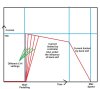
Thanks for the graph. Visual information is always good. I understand the concept of ramping and it's depiction in the graph.
When I start off in level 1 or 2, I think can feel the motor ramp up for a couple of seconds (with C14 = 2). It's hard to say if this effect changes when C14 is changed since the change in motor assist strength dominates. To explain this, I've added to the graph to show what I am experiencing (subjectively):
Important: The levels shown represent C14 = 2 (default). The differences between levels 1 to 4 are meant to be equal, whereas the differences between level 0 (off) and level 1, and between level 4 and level 5, are meant to be larger.
If I select C14 = 1, then levels 1 to 4 move downwards, i.e. they become weaker. Level 5 remains unchanged. The motor feels distinctly weaker than C14 = 2, except in level 5. There is a bigger and very noticeable step up in power between levels 4 and 5.
If I select C14 = 3, then levels 1 to 4 move upwards, i.e. they become stronger. Level 5 remains unchanged. The motor feels distinctly stronger than C14 = 2, except in level 5. There is a smaller step up in power between levels 4 and 5.
These changes in power are not minor and are experienced throughout a ride, not just when starting off.
In level 1, ghost pedalling, the maximum speeds achieved on the same stretch of level road and same wind conditions (i.e. little or none) vary significantly depending on C14 setting.
Level 1 is useful in a headwind when C14 = 2, but too feeble when C14 = 1. In the recent strong headwinds along the coast road, which I ride frequently, I've found myself using Levels 1 and 2 (C14 = 2), or levels 2 and 3 (C14 = 1).
I've attached a copy of the latest LCD3 manual that I can find (V4.0, 08/10/2022). The description of the C14 settings is: "Assist strength of intelligent pedal motor" (Values: 1 = Weak, 2 = Normal, 3 = Strong). Ramping settings appear in C5 (= 0, 1, 2). I have yet to try these out and have left C5 = 10 throughout.
I hope this makes my previous posts a bit clearer.")
When I start off in level 1 or 2, I think can feel the motor ramp up for a couple of seconds (with C14 = 2). It's hard to say if this effect changes when C14 is changed since the change in motor assist strength dominates. To explain this, I've added to the graph to show what I am experiencing (subjectively):
Important: The levels shown represent C14 = 2 (default). The differences between levels 1 to 4 are meant to be equal, whereas the differences between level 0 (off) and level 1, and between level 4 and level 5, are meant to be larger.
If I select C14 = 1, then levels 1 to 4 move downwards, i.e. they become weaker. Level 5 remains unchanged. The motor feels distinctly weaker than C14 = 2, except in level 5. There is a bigger and very noticeable step up in power between levels 4 and 5.
If I select C14 = 3, then levels 1 to 4 move upwards, i.e. they become stronger. Level 5 remains unchanged. The motor feels distinctly stronger than C14 = 2, except in level 5. There is a smaller step up in power between levels 4 and 5.
These changes in power are not minor and are experienced throughout a ride, not just when starting off.
In level 1, ghost pedalling, the maximum speeds achieved on the same stretch of level road and same wind conditions (i.e. little or none) vary significantly depending on C14 setting.
Level 1 is useful in a headwind when C14 = 2, but too feeble when C14 = 1. In the recent strong headwinds along the coast road, which I ride frequently, I've found myself using Levels 1 and 2 (C14 = 2), or levels 2 and 3 (C14 = 1).
I've attached a copy of the latest LCD3 manual that I can find (V4.0, 08/10/2022). The description of the C14 settings is: "Assist strength of intelligent pedal motor" (Values: 1 = Weak, 2 = Normal, 3 = Strong). Ramping settings appear in C5 (= 0, 1, 2). I have yet to try these out and have left C5 = 10 throughout.
I hope this makes my previous posts a bit clearer.
Attachments
-
3.5 MB Views: 7
Last edited:
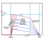
Does the amended graph below represent the lower (blue) power levels better with current eventually being limited by back emf only, due to the controller being unable to supply any more current?
I'm not sure why the first red segment (level 5) is sloping. If, in the highest power level 5 , the controller provides 15A (controller maximum), with pulse widths increasing progressively to maintain that value as speed and back emf increase until current is being delivered 100% of the time, should the first red segment not be level rather sloping? I've probably missed something and would appreciate being put right.
Once cumulative pulse widths reach 100% of time, rising back emf and falling net voltage cause the steeper red segment because the controller can no longer maintain the current.
Since the lower power levels (blue lines) merely represent lower current limits, the controller can maintain them at higher speeds before pulses occupy 100% of the time and the target current can no longer be maintained. Although I have now drawn the blue lines straight rather than kinked, I have kept them parallel to the first red line (level 5), but should they be level or sloping? And why?
I appreciate that soft start profiles are superimposed, however it's the ongoing behaviour that interests me rather than the first few seconds.
Thanks in advance for any answers.
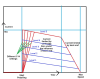
Last edited:
The blue lines would be horizontal. I've never checked level 4 - maybe it dips off a bit as the speed goes up. You should watch your LCD to see what happens. On the lower levels, the current is exactly flat, regardless of speed until the back emf limits it. The chart below is an actual record of what happens with a KT controller. The orange line is watts and the green is current, which ar exactly sychronised because the voltage was constant during that record. You can see that I used three levels during the record. The bits where it goes up and down is because I paused pedalling or hit the speed limit. I had it set with C14=1 or whatever the default minimum is, so no ramp:Does this amended graph better represent current limited by back emf only, due to the controller being unable to supply any more current? I.e. Blue lines represent 36V pulses for up to 100% of time?
View attachment 55119
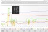
Interesting graph...
Since the current is constant for each power level, regardless of speed/back emf variations, the controller must be compensating by increasing the pulse widths to maintain a constant current. Once speed/back emf have increased to the point where current is being supplied 100% of the time, further compensation is not possible and current declines according to any further increase in back emf.
Since the current is constant for each power level, regardless of speed/back emf variations, the controller must be compensating by increasing the pulse widths to maintain a constant current. Once speed/back emf have increased to the point where current is being supplied 100% of the time, further compensation is not possible and current declines according to any further increase in back emf.
The controller is limiting the speed to 15mph, so you can't see any effect of back emf.Interesting graph...
Since the current is constant for each power level, regardless of speed/back emf variations, the controller must be compensating by increasing the pulse widths to maintain a constant current. Once speed/back emf have increased to the point where current is being supplied 100% of the time, further compensation is not possible and current declines according to any further increase in back emf.
I don't believe that the controller has the intelligence to adjust current other than the global limit. I'm pretty sure that at each power level it gives pulses at a fixed sine-wave pattern and duty cycle, with a different duty cycle at different PAS levels. Any effect of back emf wouldn't be noticed at those low power levels and speeds.
I think you are correct. The software has current control loops as shown even in basic controller below and the duty cycle is constantly been adjusted. The shunt is used to generate a current signal which is connected to one of the analogue inputs of the micro-controller.Since the current is constant for each power level, regardless of speed/back emf variations, the controller must be compensating by increasing the pulse widths to maintain a constant current. Once speed/back emf have increased to the point where current is being supplied 100% of the time, further compensation is not possible and current declines according to any further increase in back emf.
By the way, I like to set C14 =3 as it scales up the P1 to P4 settings only and reduces the 'Gap' between P4 and P5 by increasing the P4 value in my case from about 55% to about 70%.
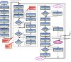
That loop is for throttle control, not PAS. Is it from the open source firmware project?I think you are correct. The software has current control loops as shown even in basic controller below and the duty cycle is constantly been adjusted. The shunt is used to generate a current signal which is connected to one of the analogue inputs of the micro-controller.
By the way, I like to set C14 =3 as it scales up the P1 to P4 settings only and reduces the 'Gap' between P4 and P5 by increasing the P4 value in my case from about 55% to about 70%.
View attachment 55314
I've been looking online for explanations of PWM current control. Although I haven't found anything e-bike specific, I keep coming across graphs like Fig 2 of the Wikipedia article "Pulse-width Modulation":
Figure 2
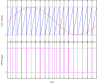
"The simplest way to generate a PWM signal is the inter-sective method, which requires only a sawtooth or a triangle waveform (easily generated using a simple oscillator) and a comparator. When the value of the reference signal (the red sine wave in figure 2) is more than the modulation waveform (blue), the PWM signal (magenta) is in the high state, otherwise it is in the low state."
The saw-tooth or triangular waveform determines the frequency of the PWM pulses, say 20kHz.
The sine-wave frequency and timing are determined and synchronised using the motor Hall sensor outputs.
Sine-wave frequency is likely to be less than 1kHz (c. 550Hz max in my motor) depending upon motor design, reduction gearing and road speed. This implies at least 20 PWM pulses per sine-wave cycle: 10 pulses in the upward part and 10 pulses in the downward part, with the actual number of pulses per cycle increasing as rpm falls.
The sine-wave amplitude (height) could be determined by the current required for a particular PAS setting and controlled by a feedback loop. The red line on the graph shows full power. For lower PAS levels the red sine-wave curve would be correspondingly flatter, with the maximum pulses widths being reduced accordingly.
At PAS level 1 the current required might be, for example, 20% of the maximum current allowed by the controller. This could be interpreted as PWM pulses being 20% on and 80% off. This means there is plenty of scope to increase the pulse widths so as to maintain current and torque as back emf increases. This could be achieved simply by varying the sine-wave amplitude (height) via a feedback loop.
It's probably more complicated than that, but hopefully these basic ideas are somewhere near the mark.
Figure 2
"The simplest way to generate a PWM signal is the inter-sective method, which requires only a sawtooth or a triangle waveform (easily generated using a simple oscillator) and a comparator. When the value of the reference signal (the red sine wave in figure 2) is more than the modulation waveform (blue), the PWM signal (magenta) is in the high state, otherwise it is in the low state."
The saw-tooth or triangular waveform determines the frequency of the PWM pulses, say 20kHz.
The sine-wave frequency and timing are determined and synchronised using the motor Hall sensor outputs.
Sine-wave frequency is likely to be less than 1kHz (c. 550Hz max in my motor) depending upon motor design, reduction gearing and road speed. This implies at least 20 PWM pulses per sine-wave cycle: 10 pulses in the upward part and 10 pulses in the downward part, with the actual number of pulses per cycle increasing as rpm falls.
The sine-wave amplitude (height) could be determined by the current required for a particular PAS setting and controlled by a feedback loop. The red line on the graph shows full power. For lower PAS levels the red sine-wave curve would be correspondingly flatter, with the maximum pulses widths being reduced accordingly.
At PAS level 1 the current required might be, for example, 20% of the maximum current allowed by the controller. This could be interpreted as PWM pulses being 20% on and 80% off. This means there is plenty of scope to increase the pulse widths so as to maintain current and torque as back emf increases. This could be achieved simply by varying the sine-wave amplitude (height) via a feedback loop.
It's probably more complicated than that, but hopefully these basic ideas are somewhere near the mark.
Last edited:
Related Articles
-
 Swytch announce new conversion kit with ‘pocket-sized’ battery
- Started by: Pedelecs
-
 New Swytch launches on Indiegogo, raises £100k in first hour
- Started by: Pedelecs
-
 Swytch to unveil 70% smaller, 50% lighter conversion kit
- Started by: Pedelecs