First time build thread 36v 500w bafang /36v 20ah

iain85

Pedelecer
Aug 5, 2010
187
4
Just to introduce myself. My name is Iain and have been lurking on this forum for a while. I've been asking simple newbie questions and have got some valuable help of a number of members so thank you everyone so far.

I have been looking for a predominatly off road set up with good pulling power and longevity to carry me across the Kent country side and decided to go for the bafang setup as suggsested on this forum.
Now the order was placed just before New year and today it has arrived! Unbelievable timing and great service from Bms!
So I was greeted by Dhl with my parcel, however they wanted the princely sum of £27 duty. (god bless the Chinese !) This was far below my calculation so payed on the spot and got my slightly damaged box of bits.

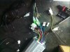
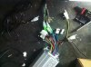
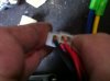
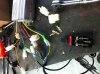
I am sitting here just unravelling the parts and have to say the quality looks good so far.

There doesn't seem to be any instructions so will have to work it out later but for now work is calling and the fun will have to start later.
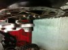
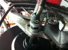
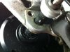
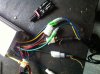
Il post a pic of the bits and of course on going pics as the build progresses.

Thanks for any help/encouragement received in advance as I have no doubt that il be asking some more newbie questions.

Kind Regards,

Iain
 

iain85

Pedelecer
Aug 5, 2010
187
4
Forgot to say/ask! Does anyone have a wiring diagram or instruction book for this kit?
 

stuvy

Finding my (electric) wheels
Jan 2, 2013
17
0
Sorry i cant be of help,

What spec kit did you go for?

Can i be rude to ask what it set you back too? a rough ball park figure will be fine
 
D

Deleted member 4366

Guest
There's no need for a wiring diagram. Everything should clip together with one exception. The thin red wire from the controller needs battery voltage to activate the controller. This is what I do. Cut it half way down and join the controller side to the two joined wires from the throttle. I think brown and green but probably wrong. Join the other side of the cut red wire to the remaining spare wire from the throttle. Yelow? The end of the thin ted wire in the connector has to be bridged somewhere to the thick red wire, so if you use the three spade connector provided for the battery, you make a bridge wire between th pins. The red button will then work like an on/off switch for the controller, but you need a proper high power switch or disconnection if you want to leave the controller off for hours or more because there will still be some drain from the battery. The throttle LEDs will go on/off with the controller.. Always check for matching colours either side of all connectors before powering up.
 
D

Deleted member 4366

Guest
There's no need for a wiring diagram. Everything should clip together with one exception. The thin red wire from the controller needs battery voltage to activate the controller. This is what I do. Cut it half way down and join the controller side to the two joined wires from the throttle. I think brown and green but probably wrong. Join the other side of the cut red wire to the remaining spare wire from the throttle. Yelow? The end of the thin ted wire in the connector has to be bridged somewhere to the thick red wire, so if you use the three spade connector provided for the battery, you make a bridge wire between th pins. The red button will then work like an on/off switch for the controller, but you need a proper high power switch or disconnection if you want to leave the controller off for hours or more because there will still be some drain from the battery. The throttle LEDs will go on/off with the controller.. Always check for matching colours either side of all connectors before powering up. Fot the pedal sensor if you can, even though it's not much use with standard setup.

Show us some photos before, during and after build.
 

iain85

Pedelecer
Aug 5, 2010
187
4
Thanks D8ave, will have another look although from briefly looking earlier there seemed to be a surplus of cables after offering up all the components supplied. I'm sure il get to the bottom of it .
When you talk about a high power switch do you have anything in mind?

I've got a little bit of time as the freewheel won't be here until 14th at the earliest.
Yes pictures will be supplied to supplement the build thread.
 

iain85

Pedelecer
Aug 5, 2010
187
4
1, Throttle
2, Brake cut of switchs
3, ?
4, ?
5, To the battery I assume
6 and 13 [Paint error!] Wires going to the hub
7, ?
8, There are 2 of these wires again ?
9 and 10, Unsure although these connectors seem to fit the throttle connector despite the wire colours not coresponding
11 and 12, 11 seems to spur off 12, although unsure as to where these go
13, see 6!

The black wire below 12 is connected to the pedal assistance sensor.

Any help would be appreciated. I have contacted Bms to see if they have any instructions/wiring diagrams in the meantime.
 

Old_Dave

Esteemed Pedelecer
Sep 15, 2012
1,211
2
Dumfries & Galloway
2 and the other 2 (brakes) to 11 & 12
13 (5 wires) go to the 6 pin plug, match the colours
1 looks like it goes to 4

Your picture would be better if the connectors were fanned out so that size and number / colours could be seen better.

You may have 4 single wires, 2 of each colour... These would be speed limit and cruse control leave them unconnected for now


Sent from my iPhone using Tapatalk
 
Last edited:

iain85

Pedelecer
Aug 5, 2010
187
4
Thanks Dave, I am hoping to get some time tommorow to have a look so thanks for the help. 1 seems to fit in to both 9 and 10 with the wires not corresponding in colour.
Any idea what 5 is? I assume to the battery but the connector seems wrong?
 

Old_Dave

Esteemed Pedelecer
Sep 15, 2012
1,211
2
Dumfries & Galloway
Or you could just click the link I posted above which will take you straight to the relevant page :p

Or maybe d8veh is just showing that the link is there on the main page when i didnt bother saying where my link came from.....lol


Sent from my iPhone using Tapatalk
 
D

Deleted member 4366

Guest
Or you could just click the link I posted above which will take you straight to the relevant page :p

Or maybe d8veh is just showing that the link is there on the main page when i didnt bother saying where my link came from.....lol


Sent from my iPhone using Tapatalk
I take so long to do my posts that you'd done two before I could hit the "post" button
 

iain85

Pedelecer
Aug 5, 2010
187
4
Cheers chaps, I think im getting there with it. I have posted a pic below to show what ive done with the wiring to see if you think its ok?

Oh yeah Ive swapped the Kona with my Mrs and it will now be a GT mountain bike as it has disc brakes :D Unfortunatly the middle triangle is slightly to small for the battery so I will mount the battery on a rear rack.

I have decided to bypass the pedal assist function for now in the name of simplicity. Also I have chose not to connect the brake cut of switchs as the brakes will be hydraulic and figured I would just shut the throttle off instead : ] Do you think this would pose any problems electrically? Also what is the high voltage brake wire for? [single blue wire]

On the throttle connection them is a redundant yellow wire which is not part of the connector. Any ideas what this is for ? In the same pic the hall sensor wires are pictured. There is an addtional white wire here that doesnt seem to go any where? Any ideas?

Last issue on the electric side im coming across is the power supply to the controller from the battery. By the looks of things, I have to make up a lead from the plug connector on the battery. However on looking at the connector block there seems to be black [neutral] where earth would be? and the small red wire where neutral should be? Any clue how I should wire this up? Do I need to make a lead up?


On to the mechanical side the wheel fitted more or less in to the drop outs. I expect I will have to do a small amount of filling to allow the axle to fit snugly into the dropouts.
There is a gap to the disc brake side which I will put spacers on to pack it out.
On the cassette side worringly the spacer seems to be the wrong way round which will prevent me from tightning the nut up adequately. I expect I will just have to cut the spacer off? Also the nut supplied will only allow you to tighten to the end of the nut as it becomes narrower? will I have to some how space this side? bearing in mind the power cable comes through? Pics will follow
 

iain85

Pedelecer
Aug 5, 2010
187
4
Forgot to say, all wires in the controller pic with a zip wire around them I believe are redundant. Although for now I have left the high voltage brake line out until I find out whar its for!