First time build thread 36v 500w bafang /36v 20ah

D

Deleted member 4366

Guest
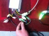
The thin white wire is spare unless there's a teperature sensor in the motor. You can check with a resistance meter. If it's open-circuit, clearly not connected. If it has resistance, there's a sensor. I reckon open circuit.

Looks like you got a slightly different throttle to normal. Yellow is for the LEDs and goes to any battery +ve.

There will be no problem leaving the brakes disconnected other than safety.

The high voltage brake wire is one that requires 5v to switch the controller off. If you were using the alarm output of some monitoring device, it might be useful. All normal switches including those hidden wire ones go low (0v).

You have the bits to make a battery connector adapter. Solder a thick piece of wire to each side of the kettle socket. Chuck the screws, they only get in the way. Solder the other ends to a couple of those spades with the white connector. Solder a short thinner wire from the red spade to the third spade. Clip the spades in to the corresponding places in the white housing. Check very carefully that you have +36v on the side that connects to the thick red controller wire before connecting. If you get it wrong, you'll need a new controller.

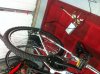
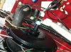
The two anti-rotation washers go on the inside of the drop-outs.

You haven't got your free-wheel on yet, which is why you appear to have a lot of space!
When you've fitted the free-wheel, make sure that you have long enough spacers up the middle that it doesn't get clamped when you do up the wheel-nut. You shouldn't need to cut anything unless you want to change to single-speed.
 

iain85

Pedelecer
Aug 5, 2010
187
4
Thanks D8ave.

Seem to recall you mentioning a switch from the thin red wire. Do I need this if I intend to unplug the kettle connector when not in use?

So I could solder the yellow wire of the throttle to the controller side thin red power supply?

Makes sense about the anti rotation washers now! Sorry I meant the extra space on the disc brake side. The free wheel you said about [Dns?] is that a special brand or the alternative to cassete mechanism?

Sorry for all the questions, just don't want to ****** it up.

Right im off to warm the soldering iron up!
Cheers,

Iain
 
D

Deleted member 4366

Guest
You can solder the yellow to the thick or thin red wires. If you put a switch on the connector bridge wire, it would work as a "standby" switch for your controller. With the yeloow wire on the controller side of it, the LEDs would go on/off with the controller. Without the switch, they'll be on all the time you're connected to the battery. You don't need a standby switch if you have no PAS, but handy for short stops at the pub.

You should be able to get an 11T DNP free-wheel from Cyclezee for about £25.
 

iain85

Pedelecer
Aug 5, 2010
187
4
Ta D8ave, Right flylead soldered up as you said. Ive used 2.5mm cable. hopefully its ok. Just a quick one im measuring 41v coming off the battery connector. upon opening the kettleplug from the battery, the 3rd pin [where you'd expect earth] isnt connected anywhere but there is what looks to be the battery negative coming from the controller going to this pin? just unsure as to the reason for this? Ill take some pics tommorow. off to the mother inlaws now sadly : @
 

Old_Dave

Esteemed Pedelecer
Sep 15, 2012
1,211
2
Dumfries & Galloway
BMS make their own logic as to where the 2 wires go on the battery connector, if on the section that's connected to the battery E is used, then you will have to use E on the part that goes to the controller....

Just change the connections on the plug & socket as required.


Sent from my iPhone using Tapatalk
 
Last edited:
D

Deleted member 4366

Guest
On all the ones I've seen, only the outer two pins are used.
 

iain85

Pedelecer
Aug 5, 2010
187
4
Hi all update and question time : ]

Right, made up flylead and worked out polarity so thats ok. I have connected it all up but it doesnt seem to want to play ball. The lights are illuminated on the throttle and have checked to see and have 42V on the controller thick red wire but no action at the wheel. There is no vlotage at the thin red wire, could this be the problen or indicate anything?
I have checked and double checked all connections and unsure where to check for voltages to find where the problem lies. Any clues?

I have attached a pic so you can see my wiring.


controller wiring lights.jpgbike and controller.jpg
 

Old_Dave

Esteemed Pedelecer
Sep 15, 2012
1,211
2
Dumfries & Galloway
Is the thin red wire you are referring to on the socket from the battery to the controller .... ?

If so, then that the problem..

Black is battery -
Red (thicker one) is battery +
Red (thinner one) is also battery + and will switch the controller on when its connected to the thicker red wire.. so between the thinner and thicker a link is required which is normally done via a switch, but for this test.. a paper clip or short length of wire stuffed into the holes will surfice (making sure that you are not shorting + to -, but just providing + to both the thick and thin red wires)
 
Last edited:
D

Deleted member 4366

Guest
Hi all update and question time : ]

Right, made up flylead and worked out polarity so thats ok. I have connected it all up but it doesnt seem to want to play ball. The lights are illuminated on the throttle and have checked to see and have 42V on the controller thick red wire but no action at the wheel. There is no vlotage at the thin red wire, could this be the problen or indicate anything?
I have checked and double checked all connections and unsure where to check for voltages to find where the problem lies. Any clues?
You don't have any power to the thin red wire. Assuming for your bit of mains lead that the brown is +36v and the blue is 0v, the yellow/green one is connected to the middle pin that doesn't have a wire on the other side. You should cut the yellow/green about 2" to 3" from the controller connector and loop it into the thick red wire on the same connector and then it'll work.
 
D

Deleted member 4366

Guest
The bit of mains lead that you've used is a bit too thin for normal operation, although it'll be OK for testing. You should be using wire reated at 30 amps. It's also looks to be too long. You need to make all wires between the battery and controller as short as possible. 14gauge OK for short lengths otherwise 122g.
1000mm Flex Silicone Wire 12AWG for battery (Red+black) | eBay
 

iain85

Pedelecer
Aug 5, 2010
187
4
axle nut clearance.jpg


Thanks chaps, She is alive and working!! Unfortunatly im away with work for a few days, but will get on to making it permanant along with the new cable as suggested.

Ok that takes care of the electrics I think! Any ideas on the deraillier side nut only going on to this depth? I guess about an 15-20mm of spacers will be required but due to the power cable they cant be any normal washer. Is there such thing as a C shaped washer? Alternativly, can the axle be moved so across so that there is more on the disc brake side? Anyone else come up against this?
Cheers again,
 

jackhandy

Esteemed Pedelecer
May 20, 2012
1,820
323
the Cornish Alps
T. You should be using wire rated at 30 amps. It's also looks to be too long. You need to make all wires between the battery and controller as short as possible. 14 gauge OK for short lengths otherwise 12g.
My bikes are all 36v, nominally 250w; (14a, 16a & 18a controllers).

Does the above hold good for my cables, or is lighter guage going to be suitable?

Hoping this question's safe from luddites buried here in this thread :rolleyes:
 
D

Deleted member 4366

Guest
My bikes are all 36v, nominally 250w; (14a, 16a & 18a controllers).

Does the above hold good for my cables, or is lighter guage going to be suitable?

Hoping this question's safe from luddites buried here in this thread :rolleyes:
I'd use 14 gauge, but for battery and motor phase wires, it's always a case of the thicker the better.
 
D

Deleted member 4366

Guest
View attachment 4804

Ok that takes care of the electrics I think! Any ideas on the deraillier side nut only going on to this depth? I guess about an 15-20mm of spacers will be required but due to the power cable they cant be any normal washer. Is there such thing as a C shaped washer? Alternativly, can the axle be moved so across so that there is more on the disc brake side? Anyone else come up against this?
Cheers again,
If that nut doesn't go all the way down to the drop-out, something is wrong. There must be a bit of damage or distortion of the thread. You need to check it carefully and file away what's stopping the nut. It won't get enough grip where it is because of the wire slot, and if you try and tighten it there, it could do some serious damage to the axle.

You can't do anything about moving the disc side because the disc has to be in the right position for the caliper. If your rim isn't central, which how it normally is (about 1 to 2 cm off-centre), you need to dish the wheel.
 

iain85

Pedelecer
Aug 5, 2010
187
4
carrier mounting.jpgbrake disc.jpgCheers D8ave, The problem seemed to be a badly manufactured nut. After taking a file to it the nut went on swimmingly. After fileing the dropouts slightly the wheel sat in there snugly and is now all done up. The disc brake also fitted on perfectly! I also picked up a freewheel, albeit 7-speed so the chain is ready to go back on.

I have now mounted the rack and bootbag to enclose the battery and controller. I have wrapped foam around the battery and secured it well with zip ties and feels very stable.
I plan to make a board for the controller to sit on and mount this on top of the battery.
Does the controller get hot? Due to the bag size the controller will just fit and is likely to come in to contact with bag. I assume this will be ok and won't suffer with overheating?

I also went into the electrical suppliers and explained about the project. I said it needed to be rated for 30amps continuous and 36v. They have supplied me with 6mm cable. This sound ok?

Next step [Hopefully tommorow!] is to fit the controller and rewire the plug to contoller with the new cable. If I have time I will fit the throttle and take her out for a spin!

Cheers all

Some pics
 

Jeremy

Esteemed Pedelecer
Oct 25, 2007
1,010
3
Salisbury
6mm² is fine. As d8veh says, bigger is better, as it isn't the cable current rating that's important here, it's the allowable voltage drop. A cable rated at 30A may well drop far too much voltage over a run from a rear mounted battery to a front hub motor, for example.

For example, 14g (about the minimum size of cable to use, even on a low power ebike) has a resistance of about 8.4mohms per metre, which, for a one metre run of double cable (pos and neg) will give a power loss that's about the same as a cheap controller, or about double the power loss of a good controller.

If you had a 2 metre run of 14g cable (4m in total) and 20A current, then you're going to waste around 13.44 watts in it. At 30A you'd waste 30.24 watts in the cable. Using your 6mm² wire, at around 3.08mohms per metre, brings the losses at 20A down to 4.93 watts and 11.09 watts at 30A, a useful power saving.
 

iain85

Pedelecer
Aug 5, 2010
187
4
6mm² is fine. As d8veh says, bigger is better, as it isn't the cable current rating that's important here, it's the allowable voltage drop. A cable rated at 30A may well drop far too much voltage over a run from a rear mounted battery to a front hub motor, for example.

For example, 14g (about the minimum size of cable to use, even on a low power ebike) has a resistance of about 8.4mohms per metre, which, for a one metre run of double cable (pos and neg) will give a power loss that's about the same as a cheap controller, or about double the power loss of a good controller.

If you had a 2 metre run of 14g cable (4m in total) and 20A current, then you're going to waste around 13.44 watts in it. At 30A you'd waste 30.24 watts in the cable. Using your 6mm² wire, at around 3.08mohms per metre, brings the losses at 20A down to 4.93 watts and 11.09 watts at 30A, a useful power saving.
Thanks Jeramy, That makes sense now. I envisage the cable length to be less that 6 inches so power loss should be low.
 

Jeremy

Esteemed Pedelecer
Oct 25, 2007
1,010
3
Salisbury
Worth noting that the current in the motor phase wires will be two or three times that in the battery cables. The controller works like a very efficient transformer, and changes the higher battery voltage to a lower motor voltage, but at a higher current, at every throttle setting below 100%.

It's quite normal to average around double the current in the motor phase leads, so keeping these short helps far more than keeping the battery leads short.
 

iain85

Pedelecer
Aug 5, 2010
187
4
Just an update. The kit is now fully functioning and I managed a brief test ride today.
I am pleased with the outcome and the bike pulled strongly from the off. Within approx 75 yards I was upto 22 mph. I didn't get a chance to test on the hills yet but I am keen to find this out tommorow!
I have a few finishing touches to do, like installing the chain!:eek: and a little cable route tidying but on the most part I am there.
I didn't realise the power as while pushing it from the garage I accidently twisted the throttle and I nearly flipped the bike!

I will report back with the battery longevity once I've had more time to play.

A big thanks go to D8ave, Old Dave and Jeramy. Also to anyone else who have helped along the way. I'm sure it gets tedious advising the newbies but without your help, I'm sure I would have blown the controller or worse.

So to all those who are considering a self build kit, Go for it!

Last question! What is the best way to look after the battery? (allow total discharge before recharging or charge after every ride? Charge /store inside or outside on the cold? Etc etc)

Pics to follow soon..
 

Old_Dave

Esteemed Pedelecer
Sep 15, 2012
1,211
2
Dumfries & Galloway
Well done Ian :D

I charge after every ride, cos the next ride you want to go on may need a full battery.


Sent from my iPhone using Tapatalk