

Well flipping the whole disc would achieve the same, did that and makes no difference. The sensors are handed and don’t think there’s a way to change that, unless one knows how to tweak an electronic circuit that isOne thing you could try. I haven'tdone it myself, but theory says it should work. You can prise out each magnet and reinsert it the other way up. Before starting, scratch a mark onto all the magnets on one side so that you don't get mixed up.
The magnets are just a tight fit in the plastic. It should be fairly straight forward to remove and reinsert them.
Front hub 48v motor for very hilly area
- Thread starter BidelloZ
- Start date
No. To get the right signal, you need the right polarity travelling in the right direction. At the moment, you have one of the two right. When you flip it, you have the other one of the two right, but if you flip the magnets individually, you'll have both right or both wrong. Both wrong can then be solved by flipping the complete disc.Well flipping the whole disc would achieve the same, did that and makes no difference. The sensors are handed and don’t think there’s a way to change that, unless one knows how to tweak an electronic circuit that is
OK, I will try that but I’m not convinced, besides makes no sense when it comes to Faraday’s laws.No. To get the right signal, you need the right polarity travelling in the right direction. At the moment, you have one of the two right. When you flip it, you have the other one of the two right, but if you flip the magnets individually, you'll have both right or both wrong. Both wrong can then be solved by flipping the complete disc.
Will report back and I actually hope I’m wrong
")
Rethinking this, you suggest that the magnets are arranger in a staggered array on the disc? Meaning, they are alternating north and south poles? If so, only half of the magnets should be flipped, so to obtain an asymmetric array = all north or south poles on one side of the disc.No. To get the right signal, you need the right polarity travelling in the right direction. At the moment, you have one of the two right. When you flip it, you have the other one of the two right, but if you flip the magnets individually, you'll have both right or both wrong. Both wrong can then be solved by flipping the complete disc.
Only if the disc is built with staggered poles of the magnets then by flipping half of the magnets we can achieve asymmetry and thus differentiate between the two faces of the disc.
I’m not good with electronics but I wonder whether the two hall sensors one next to another in the little device above are built in a circuitry in such way to differentiate between two directions. It would be easy to do that, by having the circuit transmit a signal only when the two hall sensors detect movement in one direction. Besides, both north and south poles of a magnet do generate a voltage in a hall sensor, albeit different.
Anyhow will experiment a bit, if anything for the sake of it
That's how it's done with the sensors used in most kits.I’m not good with electronics but I wonder whether the two hall sensors one next to another in the little device above are built in a circuitry in such way to differentiate between two directions. It would be easy to do that, by having the circuit transmit a signal only when the two hall sensors detect movement in one direction.
Fault finding is pretty straightforward (assuming that you haven't messed with the magnets in the disc) -
1 Nothing happens with pedals turned in either direction
a) magnet disc back to front
b) magnet disc too far from sensor (gap too big) or sensor not properly aligned with the circle of magnets.
2 If nothing happens after sorting a) and b) above, the the sensor, connectors or wiring is at fault.
3 If the motor starts when the pedals are turned backwards, you need to flip the direction of the hall sensor (no amount of messing with the magnets will alter this).
That.3 If the motor starts when the pedals are turned backwards, you need to flip the direction of the hall sensor (no amount of messing with the magnets will alter this).
Thanks for replying. In fact, sensor works perfectly. When pedalling backwards.
And as I thought, and you confirmed, it’s the arrangement of two hall sensors and circuitry that makes the difference, not the magnets.
And I’m sorry to disagree with you VFR400, but flipping each individual magnet is effectively like flipping the whole disc. Flipping half of the magnets would change the overall neat magnetic vector across the disc - but this is irrelevant to our quest.
Sorry, I wasn't thinking straight. You need the right polarity magnet passing the sensor in the correct direction, so the only way to get it to work is to remove the sensor from its bracket, re-drill the holes and mount it inverted. That will make it work in the opposite direction.
Yes that does work. But with the sensor flipped the hall coils are a bit too far from the magnet and to work well the sensor casing needs to rest against the magnet disc. Tried leaving a tiny gap and it works but the minimum movement will result in erratic behaviour.Sorry, I wasn't thinking straight. You need the right polarity magnet passing the sensor in the correct direction, so the only way to get it to work is to remove the sensor from its bracket, re-drill the holes and mount it inverted. That will make it work in the opposite direction.
Guess it’s best to source the RH side sensor. Found one already. Left side sensor for sale if anyone is interested
Hi all,
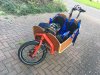
Been quite busy the last few weeks, but the bike had been finished for some time now and I have used it everyday with the kids up and down the hills.
I am now in a position to draw some solid conclusions on the two motors I’ve tested on my cargo. Actually, I had originally bought the bike with a Luna BBSHD hacked with a 52v battery which on full throttle uphill was nearing 2000w, and whilst very solid it was totally inappropriate.
So the TSDZ2 is a very nice solution for speed. By removing the 25kmh limit, it keeps assisting and I can nicely cycle around with two kids at good speeds.
However uphill it will struggle.
Conversely, the SWX02 is able to “almost” pull us uphill on the sole throttle. I say almost because although it is possible, the motor feels like it’s struggling and I think using it that way would result in quick wear/damage. When we’re on flat ground though, I can easily bypass the motor by pedalling faster than it’s max assitance. Past 18mph it won’t push anymore. But this is exactly what I wanted, raw low speed winching capability, not speed.
Both motors on the bike would have been the perfect solution. But not interesting for me, much prefer the front hub and a clean drivetrain. I’d use a mid drive on my MTB, but on a commuting city bike I believe the front hub is much nicer and silent.
Thanks all for the invaluable help.
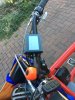
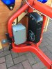
Some
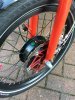
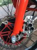
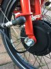
Pics of the finished product.
Been quite busy the last few weeks, but the bike had been finished for some time now and I have used it everyday with the kids up and down the hills.
I am now in a position to draw some solid conclusions on the two motors I’ve tested on my cargo. Actually, I had originally bought the bike with a Luna BBSHD hacked with a 52v battery which on full throttle uphill was nearing 2000w, and whilst very solid it was totally inappropriate.
So the TSDZ2 is a very nice solution for speed. By removing the 25kmh limit, it keeps assisting and I can nicely cycle around with two kids at good speeds.
However uphill it will struggle.
Conversely, the SWX02 is able to “almost” pull us uphill on the sole throttle. I say almost because although it is possible, the motor feels like it’s struggling and I think using it that way would result in quick wear/damage. When we’re on flat ground though, I can easily bypass the motor by pedalling faster than it’s max assitance. Past 18mph it won’t push anymore. But this is exactly what I wanted, raw low speed winching capability, not speed.
Both motors on the bike would have been the perfect solution. But not interesting for me, much prefer the front hub and a clean drivetrain. I’d use a mid drive on my MTB, but on a commuting city bike I believe the front hub is much nicer and silent.
Thanks all for the invaluable help.
Some
Pics of the finished product.
Attachments
-
 2.6 MB Views: 25
 -
 2 MB Views: 21
 -
 1.6 MB Views: 22
 -
 1.6 MB Views: 20
 -
 1.8 MB Views: 20
 -
 1.8 MB Views: 20
Very nice job.
In all aspects barring a full off road mud bike a good hub will be 'more than ' for most uses.
High torque low speed is the way to go and 18mph tbh is plenty.
Usually front wheel conversions are a poor choice but with the cargo bike, the low CofG load just behind the wheel is ideal.
In all aspects barring a full off road mud bike a good hub will be 'more than ' for most uses.
High torque low speed is the way to go and 18mph tbh is plenty.
Usually front wheel conversions are a poor choice but with the cargo bike, the low CofG load just behind the wheel is ideal.
Hi all,
Here to ask for your help once again.
I’ve added a light to my bike, that is, one powered by the main battery (in addition to my trusty Moon Orion).
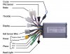
I’d want this light to be controlled by the motor controller, but I’ve found the only 48v supply from my controller is permanent, i.e. not controlled by the switch (btw the display does light up if I keep the up button pressed).
Pic of the controller wiring attached.
Sure I can add a separate switch but it’d be nice to have the inbuilt display switch.
I guess my controller can’t be controlled (excuse the pun) by the display switch?
Cheers
Here to ask for your help once again.
I’ve added a light to my bike, that is, one powered by the main battery (in addition to my trusty Moon Orion).
I’d want this light to be controlled by the motor controller, but I’ve found the only 48v supply from my controller is permanent, i.e. not controlled by the switch (btw the display does light up if I keep the up button pressed).
Pic of the controller wiring attached.
Sure I can add a separate switch but it’d be nice to have the inbuilt display switch.
I guess my controller can’t be controlled (excuse the pun) by the display switch?
Cheers
Attachments
-
 353.3 KB Views: 9
You need the light output wire from your controller, does it have one?
If so you connect it to a relay switch and the other side of the relay handles the 42v side of things.
Personally my light is on 24/24, it is a good security feature.
If so you connect it to a relay switch and the other side of the relay handles the 42v side of things.
Personally my light is on 24/24, it is a good security feature.
As far as I can tell, no. All the wires are in the pic posted above. Can’t use the blue wire for the cruise control I suppose? (Btw I removed the loop as I don’t need cruise mode).You need the light output wire from your controller, does it have one?
Yeah thought of a relay, but most automotive ones have a 12V coil - and high current contacts of course.If so you connect it to a relay switch and the other side of the relay handles the 42v side of things.
A relay with 48V coils is a big heavy thing, can’t seem to find a small one. If you do know where I can find a small 48v relay could you please share?
Thought about that, since the light is only 3W it can actually be good to have it on all the time and just control it with the switch on the battery. It’s also a good way to remember turning the battery off.Personally my light is on 24/24, it is a good security feature.
The KT controller in the link in #132 has a light output but relies on a switch for the light, unless yiu have constant running one, the lcd hasn't got light switching capability. KT rely on a separate switch like the handle bar Wuxing type you can get, the light needs to be a 6v - 60v type.
Startup Backlights and HeadlightsI've never seen a KT controller that can switch lights. You have to use your own switch.
Hold button (UP) long, the meter turns on the backlights as well as the vehicle
headlights (the Controller should have headlights driving and output functions)
Doesn't that work? I have never tried myself TBH.
https://endless-sphere.com/forums/viewtopic.php?f=2&t=75171A relay with 48V coils is a big heavy thing, can’t seem to find a small one. If you do know where I can find a small 48v relay could you please share?
The backlight comes on, but there's no transistor on the controller's pcb to switch on lights. I've seen that working in many Lishui controllers, but never a KT. Some non-KT LCDs have the transistor on their PCB and a separate connector, so you have a 5-pin and 2-pin connector attached to the LCD.. They switch on a branch of the battery voltage that supplies the LCD to that connector.Startup Backlights and Headlights
Hold button (UP) long, the meter turns on the backlights as well as the vehicle
headlights (the Controller should have headlights driving and output functions)
Doesn't that work? I have never tried myself TBH.
https://endless-sphere.com/forums/viewtopic.php?f=2&t=75171
Even when you have the switched connector for the lights, whether on the LCD or controller, the transistor that does the switching is normally very small and will blow if you put on any serious lights. They never tell you the max current you can take from that connector, so you use it at your peril.
On opening my controller there is a small PCB under shrink wrap that appears to be connected to the lighting output. What is on that PCB is a mystery but I am guessing the transistor you mention.
My idea was to use the light output wire as the low voltage side of an optical relay as per the ES thread I linked above and use 12v from a DC/DC converter to power the lights. As I want to also be able to ride my trike with the motor wheel removed the lighting circuit will optionally be powered by a 3S 5000 mAh Lipo brick.
Projected are:
- always on head and tail lights
- brake light, nothing fancy, just a second rear LED light that is turned on by the brake sensors (possibly mounted high up for SUV's...)
- indicators, mostly useful in "warning" mode - all flashing for riding in town where there are no cycle paths but a motorcycle turn signal, switch will be mounted too
- hi/lo beam headlights, again nothing fancy just a second headlight adding 70-80 lux when on the open road. This is the one I want to be able to turn on from the controller button.
Related Articles
-
 MTF Enterprises announces acquisition of EMU Electric Bikes
- Started by: Pedelecs
-
 Wisper 806T folding bike wins Which? ‘Best Buy’
- Started by: Pedelecs
-
 Sustrans calls for protected cycle lanes
- Started by: Pedelecs
-
 Amazon launch their first UK e-cargo micromobility hub
- Started by: Pedelecs
