
The torque sensor is not a common one. If it has three wires, two will power it and one is the signal. You can easily measure them to see what happens when you figure out how to switch on the controller that looks standard to me and should work like I previously explained.
Giant Twist Express RS2 - No Power
- Thread starter PointyUK
- Start date
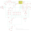
The switching doesn't look right. All the ones I've studied use a MOSFET or transistor to do the switching. The on/off needs to latch. I never analysed it, but I assumed that when you press the on/off switch, it makes a temporary connection that powers the CPU and also works as an input to the CPU. When the CPU is powered up, the default state of the output leg that controls the MOSFET is on, but when you press the on/off switch again, it works as an input that tells the CPU to make the output signal to the MOSFET go low, thus switching it off.
Also, in your schematic, the control panel would be powered all the time, which would drain the battery.
Also, in your schematic, the control panel would be powered all the time, which would drain the battery.
Anything with a soft on/off button must be powered all the time. If the MCU is in standby it will only draw a couple of ua anyway.Also, in your schematic, the control panel would be powered all the time, which would drain the battery.
I would like to try and test the motor today and just want to make sure that I don't do anything stupid. 
My other eBike is an Apollo Phaze 24v. It has a Shengyi DWG07C-FA motor, I haven't opened the motor yet as I need to get or make a special tool, but I looked at this thread and this video.
It looks like phase A is green, B is blue and C is yellow. The Giant motor is A, (brown) B (white) & C (grey) looking at the controller legend.
As I have to change the motor cable on the Apollo I bought a 9 pin extension lead, so my plane is to cut the female end of the extension lead and connect the wires to the Giant motor. I have read that you can destroy the controller if wired incorrectly so as an e precaution I will power from my bench supply with the current limiting turned down.
Any thoughts?
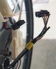
So after making the following test cable...
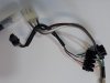
It didn't work, although it did appear the motor was trying to go backwards and drawing way to much power. After swapping the yellow and green wires round the motor worked as expected.
Of course although the colors are the same in the extension cable, it doesn't mean they are in the same order. I need to double check when I replace the Apollo cable.
I then set about testing the torque sensor, which was outputting about 1.4v on the brown wire and didn't appear to change when turning the peddles. However when holding the back wheel and trying to peddle the voltage went up to about 2.5v, so I assume this is working.
So I came up with a novel way to test the battery...
I then when for a 5 mile ride, including some steep hills at full power. The display was still showing full when I got back and the voltage was still 27v+.
Due to the lack of Giant parts in the UK and the cost of a controller (189 euros + shipping), I am leaning towards replacing things with a KT controller and display along with a PAS sensor for a fraction of the cost. Any other recommendations will also be considered.
I then when for a 5 mile ride, including some steep hills at full power. The display was still showing full when I got back and the voltage was still 27v+.
Due to the lack of Giant parts in the UK and the cost of a controller (189 euros + shipping
), I am leaning towards replacing things with a KT controller and display along with a PAS sensor for a fraction of the cost. Any other recommendations will also be considered.Go up to 36v. It'll make the bike much better.So I came up with a novel way to test the battery...
View attachment 57489
I then when for a 5 mile ride, including some steep hills at full power. The display was still showing full when I got back and the voltage was still 27v+.
Due to the lack of Giant parts in the UK and the cost of a controller (189 euros + shipping
I am sure it would, but I have to get this bike up and running as cheaply as I can for the missus.Go up to 36v. It'll make the bike much better.
At some point in the future I want to do a conversion on my Land Rover MTB and of course as it is for me, there will be no expense spared.
Having decided to replace the controller, display and torque sensor, I finally have all the parts...
BMS S06S Controller.
KT LCD4
KT-V12L
I hooked it all up, using the bench supply and it appears to be working, I just have one thing to sort out. The Giant speed sensor is just a reed switch/sensor (2 wire) can this be used with the controller? Is it just expecting a positive pulse, if so can I just connect the red/white wires? (Motor has no speed sensor wire)
Not the red wire thats +5v
google confirms
google confirms
How to wire a 2 wire speed sensor?
Wiring of speed sensor
Run one wire from the speed sensor to the RPM terminal in the rev limiter box. Run the other wire from the speed sensor to the ground location. As the two wire speed sensor is a non- polarized AC sensor, either wire can be run to the RPM terminal and/or ground.
If it's a two-wire sensor, it's a reed switch, and it will work. You connect one wire to the signal (white). The second wire will go to one of the other two, which you have to get by trial and error. Logically, if the signal wire rests high, then the other goes to ground, and vice versa.Is it just expecting a positive pulse, if so can I just connect the red/white wires? (Motor has no speed sensor wire)
Signal wire is held high, so I will try between signal and ground.Logically, if the signal wire rests high, then the other goes to ground, and vice versa.
I still haven't got round to finishing this but I have made some small progress.
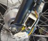
First off, as I am a bit cramped for space, I de-soldered all of the connections/wires I am not going to be using. Also as I am not going to be using the Torque sensor I wanted to remove it and sell it. At they are £150 new it has got to be worth a few quid to someone! The problem is that it holds the back wheel in place, so with my very limited skills and metal work tools I made a replacement bracket...
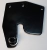
I managed to strip the thread on the original hanger bolt so I had to wait a week for a new one to turn up.
The speed sensor does appear to work between signal and ground as flashing a magnet in front of it changes the speed on the display.
I just have to put it all back together now.
First off, as I am a bit cramped for space, I de-soldered all of the connections/wires I am not going to be using. Also as I am not going to be using the Torque sensor I wanted to remove it and sell it. At they are £150 new it has got to be worth a few quid to someone! The problem is that it holds the back wheel in place, so with my very limited skills and metal work tools I made a replacement bracket...
I managed to strip the thread on the original hanger bolt so I had to wait a week for a new one to turn up.
The speed sensor does appear to work between signal and ground as flashing a magnet in front of it changes the speed on the display.
I just have to put it all back together now.
Unfortunately I need to make up new cables from both the motor and battery as I am not happy with the length of them after replacing the connectors. When checking the connectors at the motor end I noticed that the motor has 6 wires coming from the hub, the extra green wire is not included in the cable that ran back to the controller. There is also what looks like a thin black tube coming from the hub, what is this for?
I am guessing the green wire is either a temperature sensor or speed sensor and as there is a separate speed sensor on the back wheel, probably the former. How can I test this? Will it simply output a voltage from 0 - 5v based on temperature?
I am guessing the green wire is either a temperature sensor or speed sensor and as there is a separate speed sensor on the back wheel, probably the former. How can I test this? Will it simply output a voltage from 0 - 5v based on temperature?
Thanks for the reply, I haven't tested this yet, but why would they go to the expense of adding a separate speed sensor and magnet on the rear wheel if there was one built into the hub?The speed sensor in the hub will pulse 5v each time a magnet in the hub passes it .It needs to be powered by the same 5v as the motor hall sensors. The pulse can be a low one from 5v to zero or a high one from zero to 5v
Right. It must be a temperature sensor then.Thanks for the reply, I haven't tested this yet, but why would they go to the expense of adding a separate speed sensor and magnet on the rear wheel if there was one built into the hub?
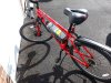
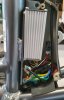
I finally got this bike finished.
As I wanted to use the original nice chunky sheaf, it was a real pain getting the new wires through, but I eventually managed it.
All cables fit inside the controller box...
I also made a rubber seal to poke the wires through, which should limit the amount of water that can splash up into the controller box. View from underneath...
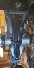
All done...
I am pretty pleased with how this turned out, in fact the bike rides better than my own! I just need to align the rear speed sensor, make sure everything is clean and lubed and all screws/bolts are tight.
As I wanted to use the original nice chunky sheaf, it was a real pain getting the new wires through, but I eventually managed it.
All cables fit inside the controller box...
I also made a rubber seal to poke the wires through, which should limit the amount of water that can splash up into the controller box. View from underneath...
All done...
I am pretty pleased with how this turned out, in fact the bike rides better than my own!
I just need to align the rear speed sensor, make sure everything is clean and lubed and all screws/bolts are tight.Related Articles
-
 MTF Enterprises announces acquisition of EMU Electric Bikes
- Started by: Pedelecs
-
 Wisper 806T folding bike wins Which? ‘Best Buy’
- Started by: Pedelecs
-
 Sustrans calls for protected cycle lanes
- Started by: Pedelecs
-
 Amazon launch their first UK e-cargo micromobility hub
- Started by: Pedelecs
