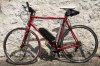
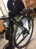
So, my latest build is finally mostly complete:
I used for the build a GSM middrive (without internal controller) from Woosh, a VESC open source controller and a Teensy as "CycleAnalyst/ForumsController".
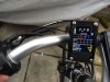
I have built a display based on a 2.2 inch LCD and also module with 5 way joystick for the controls and push throttle-button.
For power I use 12s LiPo (MultiStar 8000mAh 6s x 2 from HobbyKing in a saddle bag). I am an RC enthusiast, so I already had proper balancing chargers and know about the pros and cons of LiPos.
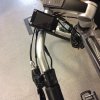
I ran the wires through the frame for a nice a clean build.
The front light is powered via a step-down module and the power can be switched on via the handlebar controls. This is the final bike:
In more detail:
I used the VESC (http://vedder.se/2015/01/vesc-open-source-esc/) as controller as it gives complete control over the settings. Via Serial communication I can get the battery current and voltage, board and Mosfet temperature, motor current and RPM.
However, as it is based for electrical skateboards, there is no input for throttles, ebrakes, PAS and displays. It has two available analog/digital pins but also a Serial port.
So I first thought I will add a CycleAnalyst for this and use one of the A2D pins as throttle input. However, then I came across the ForumsController (some info in German: http://www.pedelecforum.de/wiki/doku.php?id=elektrotechnik:forumscontroller) and thought, I can build this myself, and since I need much less functionality, i.e. I can get a lot of data already from the VESC, I basically only need the microcontroller to handle all the e-bike accessories.
The ForumsController code is nice since it already took care of a lot of things, i.e. Voltage cutoff, PID control for the output, PAS, velocity limits, range calculation, different profiles, etc.
I bought a Teensy (a 96mhz "Arduino compatible") board and adapted the ForumsController code to run on it.
I build a simple PCB to which I attached the ebrake, display, throttle and the Serial communication from the VESC. The VESC also provides one 5V 1A output which powers the Teensy and all accessories.
Below an intermediate PCB version and the VESC in a 3D printed case:
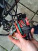
In the final version I changed the JST connectors for USB-C type connectors and wired it up using USB-C cables. I put the VESC and the teensy together in a 3D printed box on the down tube.
As a display I did not like the standard display, which is usually used, namely a Nokia 5510 display. There was already a mockup for a colour LCD, so I used the existing code and made it work with the Teensy.
Some more info on the Display (in German):
http://www.pedelecforum.de/forum/index.php?threads/forumscontroller-eine-display-diskussion.16947/page-8#post-701276
Video from the display:
https://www.dropbox.com/s/o81ibg4oab30zgj/2016-07-29 19.21.39.mov?dl=0
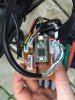
As final step I changed the throttle for a 5 way joystick and a push button throttle. I used various resistors to hook all 6 buttons up via a single Analog input. I kept the e-brake on a separate wire, just to have more reliability and I had the spare wire anyway") .
.
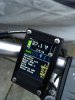
I used a USB 3.0 cable which I wired through the frame. It has 8 wires in total. The display used 6 of the wires, so I had exactly one left for the analog input for the 6 buttons and one for the e-brake. The ground is combined in the display case. I recycled the connectors of these Julet wire harnesses so I have the USB cable go inside the display case and two Julet connectors for the e-brake and the button panel, for which I 3D printed a case. See the button panel below:
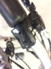
With the 5 way joystick I can increase and decrease the support in 50W steps (up/down) and change the views of the disply (left/right). A center push enters the menu, which then temporarily overwrites up/down and center for selection. The push button on the left is a push throttle, which directly sets the target support for 500W.
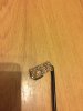
I also build a speed sensor. It is simply a Hall switch and a spoke magnet from an old bike computer.
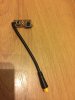
The light can be controlled via the menu, there is a step-down module hidden underneath the front fork. The module has a shutoff input, so the Teensy can switch it on and off (see the display video 2:40)
The module is like this one:
http://www.ebay.co.uk/itm/LM2596HV-DC-DC-Buck-Converter-5V-60V-to-1-25V-26V-Power-Module-48V-to-3V-5V-12V-/321512279591?hash=item4adba00e27:g:fr4AAOSwQItUCR6F
The code can be found on github, it is mostly in English, maybe here and there a German comment/text
https://github.com/daenny/Arduino-Pedelec-Controller
If you have any questions or want some more details (e.g. your German is not sufficient) let me know!
I used for the build a GSM middrive (without internal controller) from Woosh, a VESC open source controller and a Teensy as "CycleAnalyst/ForumsController".
I have built a display based on a 2.2 inch LCD and also module with 5 way joystick for the controls and push throttle-button.
For power I use 12s LiPo (MultiStar 8000mAh 6s x 2 from HobbyKing in a saddle bag). I am an RC enthusiast, so I already had proper balancing chargers and know about the pros and cons of LiPos.
I ran the wires through the frame for a nice a clean build.
The front light is powered via a step-down module and the power can be switched on via the handlebar controls. This is the final bike:
In more detail:
I used the VESC (http://vedder.se/2015/01/vesc-open-source-esc/) as controller as it gives complete control over the settings. Via Serial communication I can get the battery current and voltage, board and Mosfet temperature, motor current and RPM.
However, as it is based for electrical skateboards, there is no input for throttles, ebrakes, PAS and displays. It has two available analog/digital pins but also a Serial port.
So I first thought I will add a CycleAnalyst for this and use one of the A2D pins as throttle input. However, then I came across the ForumsController (some info in German: http://www.pedelecforum.de/wiki/doku.php?id=elektrotechnik:forumscontroller) and thought, I can build this myself, and since I need much less functionality, i.e. I can get a lot of data already from the VESC, I basically only need the microcontroller to handle all the e-bike accessories.
The ForumsController code is nice since it already took care of a lot of things, i.e. Voltage cutoff, PID control for the output, PAS, velocity limits, range calculation, different profiles, etc.
I bought a Teensy (a 96mhz "Arduino compatible") board and adapted the ForumsController code to run on it.
I build a simple PCB to which I attached the ebrake, display, throttle and the Serial communication from the VESC. The VESC also provides one 5V 1A output which powers the Teensy and all accessories.
Below an intermediate PCB version and the VESC in a 3D printed case:
In the final version I changed the JST connectors for USB-C type connectors and wired it up using USB-C cables. I put the VESC and the teensy together in a 3D printed box on the down tube.
As a display I did not like the standard display, which is usually used, namely a Nokia 5510 display. There was already a mockup for a colour LCD, so I used the existing code and made it work with the Teensy.
Some more info on the Display (in German):
http://www.pedelecforum.de/forum/index.php?threads/forumscontroller-eine-display-diskussion.16947/page-8#post-701276
Video from the display:
https://www.dropbox.com/s/o81ibg4oab30zgj/2016-07-29 19.21.39.mov?dl=0
As final step I changed the throttle for a 5 way joystick and a push button throttle. I used various resistors to hook all 6 buttons up via a single Analog input. I kept the e-brake on a separate wire, just to have more reliability and I had the spare wire anyway
. I used a USB 3.0 cable which I wired through the frame. It has 8 wires in total. The display used 6 of the wires, so I had exactly one left for the analog input for the 6 buttons and one for the e-brake. The ground is combined in the display case. I recycled the connectors of these Julet wire harnesses so I have the USB cable go inside the display case and two Julet connectors for the e-brake and the button panel, for which I 3D printed a case. See the button panel below:
With the 5 way joystick I can increase and decrease the support in 50W steps (up/down) and change the views of the disply (left/right). A center push enters the menu, which then temporarily overwrites up/down and center for selection. The push button on the left is a push throttle, which directly sets the target support for 500W.
I also build a speed sensor. It is simply a Hall switch and a spoke magnet from an old bike computer.
The light can be controlled via the menu, there is a step-down module hidden underneath the front fork. The module has a shutoff input, so the Teensy can switch it on and off (see the display video 2:40)
The module is like this one:
http://www.ebay.co.uk/itm/LM2596HV-DC-DC-Buck-Converter-5V-60V-to-1-25V-26V-Power-Module-48V-to-3V-5V-12V-/321512279591?hash=item4adba00e27:g:fr4AAOSwQItUCR6F
The code can be found on github, it is mostly in English, maybe here and there a German comment/text
https://github.com/daenny/Arduino-Pedelec-Controller
If you have any questions or want some more details (e.g. your German is not sufficient) let me know!