Help please! How can I shave the current on a KU63 controller?

Thamosy

Pedelecer
Jan 14, 2013
55
1
I wonder if anyone could spell out for me (in as much detail as possible) how to “shave the current shunt” on a KU63 controller. I’m expecting delivery of the various parts to electrify a Brompton and from reading many of the forum pages it seems others have done this to reduce current from the set 15 Amps to around 8 Amps or so.

I found a good explanation of the KU63 controller here

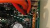
KU63 motor controller

But after ploughing through that I’m still hesitant to do anything other than disable the pedelec control (should I need to).

That web page has a bit about INCREASING the motor current, but nothing about REDUCING it. So, please, can anyone help me?

I suppose the other option might be to use the three speed option of the ku63 and ensure that only the lowest speed was ever used. Would that work?

As I understand things, the 3 speed switch is a throttle limiter so (I think) should reduce both current and voltage. But is that correct?

And then the next option might be to disconnect one of the three wires to the 3-speed switch on the controller ... I wonder would that option have the same effect as saying “never use setting III !?”
 
D

Deleted member 4366

Guest
The three-speed switch will limit your speed, but I'm not sure about the current because I always go for the speed boost option with it.

To reduce the current, you only need to file a few notches in the shunt. You need a wattmeter to see the effects. Any cheap wattmeter will do:
New Digital 60V/100A Battery Balance LCD Voltage Power Analyzer Watt Meter | eBay
Lift the motor-wheel off the ground, give it full throttle, and then usethe brake to slow it right down. You'll see the current rise to a maximum as it slows down. Is it a Tongxin motor? If so 12 amps should be OK. Only if the clutch slips do you need to reduce further.
 

Thamosy

Pedelecer
Jan 14, 2013
55
1
Hi D8veh

You must excuse me, but I’m a complete dumbo as far as electronics is concerned. I don’t know one component from another!

In the KU63 web page it talks about increasing the current and that, “A convenient way is tinning of the shunt to increase the motor current” There’s then this particular picture and lifting that picture from the page, is the part I’ve arrowed the shunt? That seems to be the only part that’s “tinned”.
(And always assuming my KU63 is the same – it is still on its way).

Shunt query.jpg

So, if I’m to file a few notches in it, would that be at random, from any particular end, and also, how deep?

I’ve used a Turnigy watt-meter on my old wheel and I’m confident about that, it’s just the “how”. And perhaps I should add that I do have a spare KU63 controller!
 
D

Deleted member 4366

Guest
The shunt is the big copper-coloured thing on the extreme bottom right of that photo, not the thing that you've arrowed, which is the LED . It looks like Albert has already filed a lot of notches in his one for whatever reason. Looking at the cut-marks in it, I'd say that he's used side-cutters to crimp it rather than file it. That's a better idea because it doesn't make filings, and you only need to remove the end-plate from the controller. Normally it looks like this:
 
Last edited by a moderator:

Thamosy

Pedelecer
Jan 14, 2013
55
1
I’ve done a bit more reading and think I now get the idea. As I understand it, basically I’m trying to increase the resistance of that bit of wire by reducing its size. I now see what you mean in the pic from the website, where the opposite had been done by adding a whole lot of copper to the shunt.

When my parts arrive (and I get it all assembled) I’ll go for the “bit at a time” approach – and the crimping sounds easier to me than filing.

Thanks, a million.
 

jackhandy

Esteemed Pedelecer
May 20, 2012
1,820
323
the Cornish Alps
Go easy with the side-cutters if you choose that method...

Don't sneeze or fart while you're squeezing, or you could bifurcate it :p
 

shemozzle999

Esteemed Pedelecer
Sep 28, 2009
2,826
686
Resistance is defined as:

r = rho x L \ A

where rho is the resistivity of the material, L is the length of the resistor, and A is the cross-sectional area of the resistor.

As you need to increase the resistance of the shunt to reduce the controller current, either you lengthen the shunt (currently fixed) or reduce the cross sectional area.

Conversely, to decrease the resistance of the shunt to increase the controller current, either you increase the cross sectional area (currently fixed) or shorten the length of the shunt (this can effectively be achieved by soldering a portion of the length of the shunt, as the solder has a lower resistivity (rho) than the shunt material it effectively shorts out the length shunt that has been soldered).

If you carefully remove the solder at a later date the shunt can be returned to its original state.
 
Last edited:

Thamosy

Pedelecer
Jan 14, 2013
55
1
I knew there'd be a fund of knowledge here.... thanks.

I'll go easy on reducing the shunt. And although the home-made measuring device looks fairly straightforward I'll maybe stick to my friend's Turnigy.

Right now I'm still waiting for the parts. Everything that should have arrived yesterday seems to be held up somewhere - maybe flight cancellations because of the storm?
 

shemozzle999

Esteemed Pedelecer
Sep 28, 2009
2,826
686
Ideally you should reduce the cross sectional area equally along the entire length of the shunt, in small steps, until you achieve the result you want. This ensures you don't create a local hot spot on the shunt and preserves the current carrying ability of the shunt.

I personally would remove the controller from the case and mask off the base of the shunt with masking tape with the sticky side up so the it can catch the filings and use a flat needle file drawing it up and down the side of the shunt exposed on the end on the pcb.
 
Last edited: