help to get started

szancsezz

Finding my (electric) wheels
Oct 25, 2014
9
1
45
Eager to ride my bike but cant make it start.

I have bought the conversion set at a local bicycle shop at china. 48v 350 w.

Trying to put the bike together with the help of my uncle.

BeFunky_2014-10-24 23.jpg

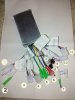
We solved the meaning of most of the cables, but still not enough to make the engine work.
Does anyone have a clue of what might number 1, 2, 10 and 12 might be?

Regards,

Oliver
 

trex

Esteemed Pedelecer
May 15, 2011
7,703
2,671
post a picture of the label on the controller case for identification.
 
  • Like
Reactions: szancsezz

trex

Esteemed Pedelecer
May 15, 2011
7,703
2,671
I am looking at this one, quite close to yours:


it will take a while to check for discrepancies.
Connector 1 seems to be the electric lock, it has the Battery + on the thick red and small red (No 2). You can verify this with a DVM, using a black wire as 0V reference, the red wire on connector 1 should show 50V.
Next step is to locate the electric lock wire, yellow on the diagram, but I can't see the colours properly on your picture. You need to connect the small red to the electric lock pin to start the controller.
Can you list the colours of the wires going to 1, 2, 10 and 12?
 

szancsezz

Finding my (electric) wheels
Oct 25, 2014
9
1
45
Despite all Trex's useful remarks, we still in trouble.

The more I think about it I see the solution in the electric lock. Astrex suggested it.
Yesterday we tried to bypass it without any luck. Today someone said that I should probably connect blue and red in number 10 to make it run.Number 12 could be regen.

Is it not possible that I simply miss an ignition set and without it, the system will not start? Hope this is not the case :)

These are the colors you asked for.
1, 2 pole connector, red, black,

2, 1 pole connector red

3, 3 pole connector brown, black, gray Power selector swith ( erő ráhatás kapcsoló)

4, 5 pole connector yellow, red, black, blue, green HAL sensor (motorban lévő mozgásérzékelő)

5, 3x1 pole connector yelloe, black, blue Motor Phase Lines

6, 2 pole Accummulator

7, 1 pole connector red (the oposite of no 2)

8, 2 pole connector white, white Speed Limit (sebesség korlát)

9, 3 pole connector black, red, yellow Pedal Sensor (pedál szenzor)

10, 2 pole connector blue, red

11, 3 pole connector red, black,green Accelerator ( gázkar)
 

trex

Esteemed Pedelecer
May 15, 2011
7,703
2,671
I suspect that the blue wire on connector 10 is the electric lock, but I am not sure.
The only way to be sure is to follow the blue wire to the circuit board. If it goes to the big 2W resistor on the board, then it's the ignition wire. Then connecting red and blue on connector 10 turns on the controller.
 

szancsezz

Finding my (electric) wheels
Oct 25, 2014
9
1
45
I see.
We followed the wires according to your suggestion.
From this connector the red is going to the big 2W resistor.
On the board, it is printed VCC. The blue wire is going to A3.

So it looks, the red wire is the ignition wire. If it is true where do I have to connect? To the GND, one of the black wires?
Thanks again!
 

trex

Esteemed Pedelecer
May 15, 2011
7,703
2,671
the ignition switch goes to Batt+ (40V) and the big 2W resistor.
The resistor is the entry point to power the 14V rail on the controller.
 

szancsezz

Finding my (electric) wheels
Oct 25, 2014
9
1
45
Dear trex,

Ok, You could see on the picture, there is connector No 7, and No 2. No7 connected directly to the red wire of the connector No 10. This is the Ignition wire. No 2 connected directly to the red wire of the connector 1. This is definitely the + edge of the accumulator. You called 40V. I checked with the DVM.


So If I connect No7 and No 2, it is what You offered. I did it, but nothing happened. I connected only the Accumulator connector, and the motor Phases connectors, and No 7, and 2. Nothing else. I think in that case the motor has to start turn slowly. But nothing happened.


Have You maybe got any other idea?


Thanks


Deák Gábor
 

timidtom

Esteemed Pedelecer
Oct 19, 2009
757
175
Cheshire
GambiaGOES.blogspot.com
New Year resolution - bit late, perhaps, but: I am never ever going to attempt building an electric bike. Ever. Chinese mechanics are talented, underrated, people. Thanks for this thread - I had been toying with the idea ...
 

Alan Quay

Esteemed Pedelecer
Dec 4, 2012
2,351
1,076
Devon
New Year resolution - bit late, perhaps, but: I am never ever going to attempt building an electric bike. Ever. Chinese mechanics are talented, underrated, people. Thanks for this thread - I had been toying with the idea ...
These problems are only due to a poorly documented, non standard controller. Had it been a ku65 (for example) the situation would have been different.
 

trex

Esteemed Pedelecer
May 15, 2011
7,703
2,671
Dear trex,

Ok, You could see on the picture, there is connector No 7, and No 2. No7 connected directly to the red wire of the connector No 10. This is the Ignition wire. No 2 connected directly to the red wire of the connector 1. This is definitely the + edge of the accumulator. You called 40V. I checked with the DVM.


So If I connect No7 and No 2, it is what You offered. I did it, but nothing happened. I connected only the Accumulator connector, and the motor Phases connectors, and No 7, and 2. Nothing else. I think in that case the motor has to start turn slowly. But nothing happened.


Have You maybe got any other idea?


Thanks


Deák Gábor
the red wires (on 1,2,7,10) usually connected directly to Batt+ and show 40V. The black wires are usually connected to Batt- (0V). What is the voltage at the blue wire after you connect to the battery?
 

szancsezz

Finding my (electric) wheels
Oct 25, 2014
9
1
45
Dear Trex,

We have moved our operation to the evening:)

The black wires connected all to the 0. The red wires are interesting: On the 1 the red is definitely the + 40V. On the 2 the red wire is the same, + 40V. On 7, the red is connected to the red wire of 10, which is VCC called, I mesured, it is 0V. And the blue wire on 10 also 0V.

What do you think could be the next step?
 

trex

Esteemed Pedelecer
May 15, 2011
7,703
2,671
It's logical to connect Batt+ to Vcc.
This connection is normally made by the LED panel or LCD.
I'd use a 200mA fuse to connect red (2, 40V) to red (7,0V). If the red on the throttle shows 5V, then red (7,0V) is the correct ignition wire because it powers up the 5V rail. Then I would remove the fuse and connect directly.
 

szancsezz

Finding my (electric) wheels
Oct 25, 2014
9
1
45
I connected the red wires 2 and 7. Now on the blue wire on 10 is 4,5V, and the red on the 11 we get 5 V (before this connection we had 0V on both.). So it looks that controller started. But nothing else connected. What to do now?
 

trex

Esteemed Pedelecer
May 15, 2011
7,703
2,671
Switch off first.
Do you have a LED panel or LCD?
If you do, connect the LCD or LED panel, try changing the settings and check the voltage bar.
If you don't, skip that step.
Then connect the motor phase wires, hall wires (if your motor has them) and throttle.
Then try the throttle.
Then connect the pedelec sensor and try it.
 

kuksoolchris

Finding my (electric) wheels
Oct 2, 2014
17
0
41
Inverness
Hi Oliver. This might be as insulting as asking if the battery is charged but. Have you tried the qr barcode to see if it links to the manufactures website and therefore the wiring diagram?