

Can you as vfr has mentioned do the voltage checks again (make sure the meter's battery is good so you get correct readings), if 36v across the board and all 10 cell groups are good then charge should occur, however you have mentioned 17v no way will the BMS allow charge at this voltage.
Help! Hi all, just bought a 'broken' ebike. Some help needed. Falcoln Turbine.
- Thread starter UnclePuncher
- Start date
Hi, sorry for the delay. I've got young kids. Things get busy.17v is what you can measure when the BMS is switched off. You'll get the true battery voltage by measuring the cell-pack directly. You said that you hd approx 3,6v per cell, which makes 36v overall, not 17v! Did you definitely get 10 cells with those voltages and not 9?
You said it's a Hailong case battery. They have a switch on them, which switches the BMS on and off, but you have nothing like that connected to the BMS in any of your photos. How do you switch the battery on without a switch?
Yes, definitely 10 sets at 3.5-3.6v (I just rechecked).
There is no switch on the case. There is a small battery meter with a button, you press it and the green light shines briefly to tell you it has power. It has 4 LEDs on it but only one of them ever lights up. It doesn't stay on for long. I tried checking the voltage at the case terminals when pressing the battery meter button but it doesn't change.
I still get 17v at the battery terminals (even without the charger attached.
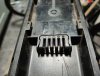
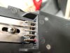
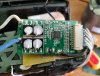
ok, if you can follow this image:Test the mosfets whilst the controller is open with no battery power.
Set meter dial to 20k or 200k ohms and probe the Black battery wire at discharge pin against the three thick phase lines you can see on the board in front of the fets, one should see about 9k ohms for each one or at least they should be all fairly close in reading. Any way out of whack (very low) means a fault.
If ok then try again against the Red discharge pin you may or may not get a similar reading but an ascending one on all or may just a 1, as long as none are zero then thee will be fine on this side.
Green is the black probe (for clarity) to Battery negative (the black wire).
Red ellipse is where I put the red probe.
I get '000' for pins A1, B1 & C1 and '1 ' (see image below - as in the default reading when the probes aren't touching anything) for all the other pins (including D1).
I don't have a Battery positive on the BMS so put the probe directly on the red wire on the end of the cell pack (that goes to the case terminal). I get '1' for every mosfet pin doing it this way.
My multimeter only has 2000 ohm and 2000k ohm settings. I did it on both and got the same readings both times. For ref its a Altai DT830A (fairly basic)
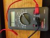
I've done it tonight and got 3.5-3.6v on all 10.Can you as vfr has mentioned do the voltage checks again (make sure the meter's battery is good so you get correct readings), if 36v across the board and all 10 cell groups are good then charge should occur, however you have mentioned 17v no way will the BMS allow charge at this voltage.
I get 35.9v before the BMS (total) and 16.9v after it (which of course goes to the case terminals and thus the bike).
I ordered one. Will fit at the weekend if I get chance.Tempted to get another BMS just to test it. This one is only £10, it doesn't have the power meter like mine does but it does have a temp thingy.
Fitted the BMS. Soldered the blade fuse in too (I'll get a proper holder for it but this is just to get it going). Battery works great. 35.8v at terminals. Now that I've got the other BMS off I can see how corroded it was, not surprising it didn't work.
Ebike still doesn't work though unfortunately. I put the battery on the bike in the cellar (where its quite dark). Bike didn't do anything (no power). So I took it off, figured I'd mounted it incorrectly and put it back on. This time the bike did something but not a good thing. Heard an electrical 'fizz' noise and I could no longer remove the battery. Eventually got it off (had to wedge it off with a piece of wood) and its welded the battery terminals a bit (well melted them - burn marks and so on). So I'm assuming there is a short somewhere.
Took the bike up into the house to inspect the damage. Tried again to check I'd not done something wrong in the dark and got the same result. Bits of the terminal connection fell out when I checked the contacts afterwards. Checked again with wires between the battery and the bike (to ensure it wasn't the battery mounting oddly) and it still shorted (about gave myself arc eye in the process).
For the record I've checked the polarity on the battery. I've definitely resoldered it correctly.
So I figure the speed controller is faulty. As mentioned previously its a PCB encased in resin so I wouldn't be able to fix it if I knew what was wrong. So I'm thinking I should buy another one and try it.
Problem is my speed controller is part of the battery mount so any 'fix' is going to look ugly and require some manual mods. Current thinking is to gut the mount and just have the battery wires run out the bottom. Then have a speed controller with all the cables in a bag on the top tube. Will require me to lengthen almost every cable though. Plus my bike uses Julet cables and the vast majority of speed controllers I find don't. So I'll be cutting and soldering wires for hours.
Unless anyone can think of anything more obvious that I may not have thought of?
Photos
Attachments
-
 4.6 MB Views: 19
 -
 4.1 MB Views: 18
 -
 4.2 MB Views: 16
 -
 3.7 MB Views: 20
You can get a replacement controller that fits in the battery mount from TopBikeKit. I would get display, throttle, pas and 4 into 1 cable as well to ensure compatability and ease of fitment. I would want to try and find that short before anything. Look for damaged cables, what display is fitted?
10S/13S/14S 36V/48V 6Mosfets Sine Wave Controller for Hailong case 52pcs cells [Hialong 1 Case Controller] - $42.75 : Zen Cart!, The Art of E-commerce
Zen Cart! 10S/13S/14S 36V/48V 6Mosfets Sine Wave Controller for Hailong case 52pcs cells [Hialong 1 Case Controller] - ★★★★★ 10S/13S/14S 36V/48V 6Mosfets Sine Wave Controller for Hailong case 52pcs cells 1--Rate Voltage:36V or 48V KT sine wave controller 2--Rated Current:7A,for 250W-350W...
www.topbikekit.com
Last edited:

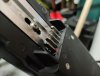
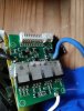
That if you don't mind me saying looks very much like reverse polarity connection and is why both contacts are burnt/melted.
Fitting/soldering the BMS in may have been incorrect or a short causing the melting internally on the battery contacts.
You need to show us the work you have carried out as it is on the battery internally.
Fitting/soldering the BMS in may have been incorrect or a short causing the melting internally on the battery contacts.
You need to show us the work you have carried out as it is on the battery internally.
Photos
Wouldn't the mutlimeter give a negative reading if it was reverse polarity?
Honestly hope it is as that'll be an easier fix.
Fair comment. It was quite late at night when I was finishing it. Didn't take any photos either. Too late to do so now but I'll endeavor to do so tomorrow.That if you don't mind me saying looks very much like reverse polarity connection and is why both contacts are burnt/melted.
Fitting/soldering the BMS in may have been incorrect or a short causing the melting internally on the battery contacts.
You need to show us the work you have carried out as it is on the battery internally.
Wouldn't the mutlimeter give a negative reading if it was reverse polarity?
Honestly hope it is as that'll be an easier fix.
When something like that happens it is due to a short of some kind, as can be seen they aren't just burnt the contact ends have melted.
I can only assume the BMS v+/v- may have been connected incorrectly or a solder joint has failed and shorted.
I can only assume the BMS v+/v- may have been connected incorrectly or a solder joint has failed and shorted.
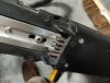
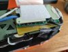
Ok. Not super easy to see but the wires are all in the correct places.
I only soldered them from the reverse side. So that may be the issue (assuming it's a double sided PCB). I'll rectify that now.
I only soldered them from the reverse side. So that may be the issue (assuming it's a double sided PCB). I'll rectify that now.
Attachments
-
 1.9 MB Views: 12
 -
 1.9 MB Views: 9
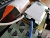
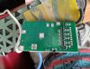
Here is a better look at the bms with the cover removed.
My soldering could be better (it's been a while) but it all seems functional.
My soldering could be better (it's been a while) but it all seems functional.
Attachments
-
 2.8 MB Views: 13
 -
 2.6 MB Views: 13
Just as a bookmark for me I'll be replacing the burnt contacts once I get it working.
They're not cheap though. £12!
They're not cheap though. £12!
Related Articles
-
 MTF Enterprises announces acquisition of EMU Electric Bikes
- Started by: Pedelecs
-
 Wisper 806T folding bike wins Which? ‘Best Buy’
- Started by: Pedelecs
-
 Sustrans calls for protected cycle lanes
- Started by: Pedelecs
-
 Amazon launch their first UK e-cargo micromobility hub
- Started by: Pedelecs
