First of all, thanks so much for your help.
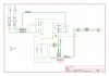
Here is a schematic I guessed out of the interconnect box. Yes 123 top are wired to 123 bottom. The 4 pin wiring is a little bit different so you'll see it on the schematic.
Anyway I think this wiring is compatible with your outputs. My interpretation of how the system works, given your outputs, is:
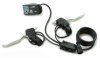
The panel is wired on pins 1234. It monitors the battery voltage on pin 1-2 and computes the remaining charge. The pin 3 drive the assistance on and off. Pin 4 is driven by the panel to 1, 2,3 volts depending of the assistance level setting. This voltage is divided by the resistor bridge. The dividing ratio changes , according to dip switch between 50% to about 10%. The divided voltage sets the maximum speed level on the controller.
But I've not really understood where the 10k pot have to be wired. I would have say between 5,6,7 like on the schematic, and as you mention, a switch is needed to stop the walking assistance (I missed that point during my guesses).
But with this scenario, there is not relation between walking assistance and the panel, which makes it not consistent with your post. (I didn't see how the 690 could drive 4 voltages with 3 position switches ???). I really missed something.
It would be nice if you could confirm whether my understanding are right or not and clarify a bit the last topic.
After several weeks of use, I also figured that even the minimal assistance level is fast for mountain biking. I have to understand the whole system so I'll try to add a lower level.