Hi

dedepanou

Just Joined
Aug 5, 2013
4
0
Hello all

Just order a 8fun evolution kit. This kit uses a Shuzhou Bafang controller and I'm interested in getting the wiring of this device. If somebody gets it, it will be nice

I will let you know how this kit behaves, as soon as the installation gets complete.

Bye
 

mountainsport

Esteemed Pedelecer
Feb 6, 2012
1,419
298
Hello all

Just order a 8fun evolution kit. This kit uses a Shuzhou Bafang controller and I'm interested in getting the wiring of this device. If somebody gets it, it will be nice

I will let you know how this kit behaves, as soon as the installation gets complete.

Welcome dedepanou, and enjoy it when the kit comes, you'll get any and everything on here and that's for free.

MS.
 

eeagles

Finding my (electric) wheels
Aug 2, 2013
5
0
Hi, Just installing this on my back, but going through some issues with the pedelec. Won't know if that works until next week as ordered a new bottom bracket - getting that right is the main problem it seems.
As for the wiring, some of the wires' colours don't match, but it's still easy to work out. The instructions are not great either, but we've managed to work it out despite this.
 
D

Deleted member 4366

Guest
Hello all

Just order a 8fun evolution kit. This kit uses a Shuzhou Bafang controller and I'm interested in getting the wiring of this device. If somebody gets it, it will be nice

I will let you know how this kit behaves, as soon as the installation gets complete.

Bye
The wiring is very straightforward. All the wires have matching connectors, so it's hard to get things wrong.

This schematic from Alien looks
http://www.alienbikes.co.uk/36V KIT Jun2010 v2.jpg
 

dedepanou

Just Joined
Aug 5, 2013
4
0
Hello all
It is not this kit. I posted a pic of the controler
kit2.jpgKit.jpg
I want to add a walking assistance and need to have the wiring of the 8 pin DIN connector.
As a first impression, this kit rocks, while being fully legal.
 
D

Deleted member 4366

Guest
I' trying to figure out what you've got. Are you saying you have or haven't got what's in the photo? What exactly d you have?
 

dedepanou

Just Joined
Aug 5, 2013
4
0
Hello

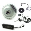
Sorry to have been a little confusing. Yes I've got what is on this pictures, ie
- A shuzu Bafang controler
- a 8fun BPM motor
- rotation sensor
- Brake handles
- led display
Every thing comes prewired. I know that it is possible to to add a walking assistance by adding a potentiometer from the interconnection box (a small piece of PCB in a plastic box, where display and brake handles cables are merged and connected to the 8 wires controller input cable). Here is a picture of it.
IMAG0787.jpg

Wires 1 to 8 at the bottom are the controller inputs. I guessed they could be :

1 +VBATT
2 -VBATT
3 Ignition
4 Speed control
5 +5V
6 Throtlle
7 GND
8 Brakes

So the walking assistance potentiometer should be wired between 5,6,7. But I would like confirmation before frying everything.

(For those who are interrested, the dip switches control the max speed).
 
Last edited:
D

Deleted member 4366

Guest
OK. I've got it now.
Can you confirm that inputs 1, 2, 3 and 4 at the top are connected directly to 1, 2, 3, 4 outputs. If so, your assessment could be correct. You can check which is throttle signal and brake with a meter, the brake is 5v, and pulled down to ground when the brake is on.

If you put a voltmeter between the green wire (4) and the black one (2), you should find that PAS level one is 1v, PAS level 2 is 2v, and PAS level 3 is 3v. You might find that if you make it 4v you get 6km/hr because that's how the 690 panel works.

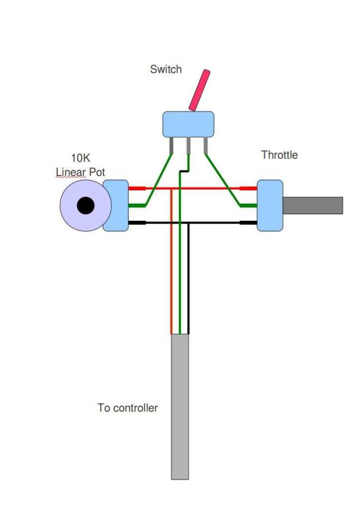
if you want to use the potentiometer, it might be better to isolate it from the throttle with a two or three position switch like this, which is how I made a cruise control:
 

dedepanou

Just Joined
Aug 5, 2013
4
0
First of all, thanks so much for your help.
ConnBoard.jpg
Here is a schematic I guessed out of the interconnect box. Yes 123 top are wired to 123 bottom. The 4 pin wiring is a little bit different so you'll see it on the schematic.

Anyway I think this wiring is compatible with your outputs. My interpretation of how the system works, given your outputs, is:
The panel is wired on pins 1234. It monitors the battery voltage on pin 1-2 and computes the remaining charge. The pin 3 drive the assistance on and off. Pin 4 is driven by the panel to 1, 2,3 volts depending of the assistance level setting. This voltage is divided by the resistor bridge. The dividing ratio changes , according to dip switch between 50% to about 10%. The divided voltage sets the maximum speed level on the controller.

But I've not really understood where the 10k pot have to be wired. I would have say between 5,6,7 like on the schematic, and as you mention, a switch is needed to stop the walking assistance (I missed that point during my guesses).

But with this scenario, there is not relation between walking assistance and the panel, which makes it not consistent with your post. (I didn't see how the 690 could drive 4 voltages with 3 position switches ???). I really missed something.

It would be nice if you could confirm whether my understanding are right or not and clarify a bit the last topic.
After several weeks of use, I also figured that even the minimal assistance level is fast for mountain biking. I have to understand the whole system so I'll try to add a lower level.
 
Last edited: