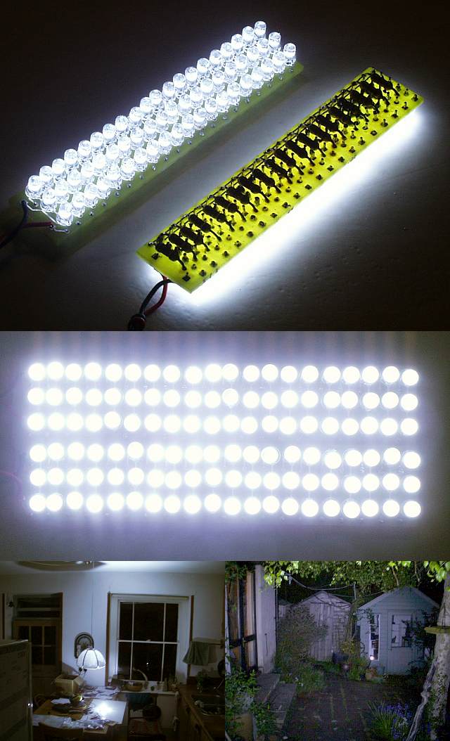
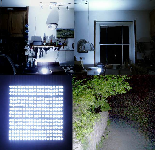
100 Watt, that's just silly!Yeah soak test is a good idea, I'll be running the LEDs from a stable 12v source, 25watt DC-DC converter which is adjustable so if I find the LEDs are burning out I can simply lower the voltage. I stuck to 120ohm resistors which is for 3 3.2v LEDs in a row each drawing 20mA, whereas the LEDs I bought are rated for 3.4-3.6v, undervolting them will extend life & reduce brightness but heck there's going to be 300 of them so it can't be all that dim!
BTW, I just found the ultimate LED bike light: 100 watt LED(but it costs £240+)
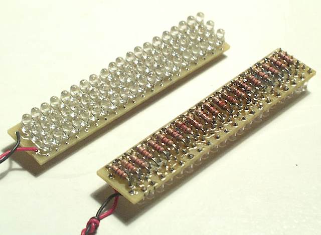
The other idea I had for your circuit was to common each of the LEDS at to it's neighbour. So instead of 20 independent strings of 3 in series you have 3x20 LEDS in parrallel arranged in a series string of 3x 20 parrallel LEDS. (language is failing me here!). That way if a single LED fails it won't take out the other 2 in its serial string as well, the extra current will simply be shared amongst the other 19 in the parallel block. Should be pretty easy to mod your PCB to get this extra resilience. (Having had to retrofit failed LEDS I'm paranoid about resilience!
)