Homemade *bright* LED light setup

Haku

Esteemed Pedelecer
Jun 20, 2007
339
4
Gloucestershire
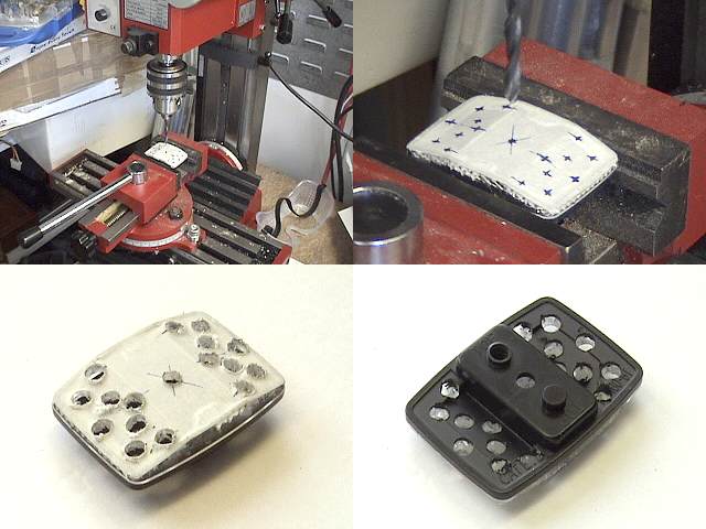
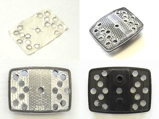
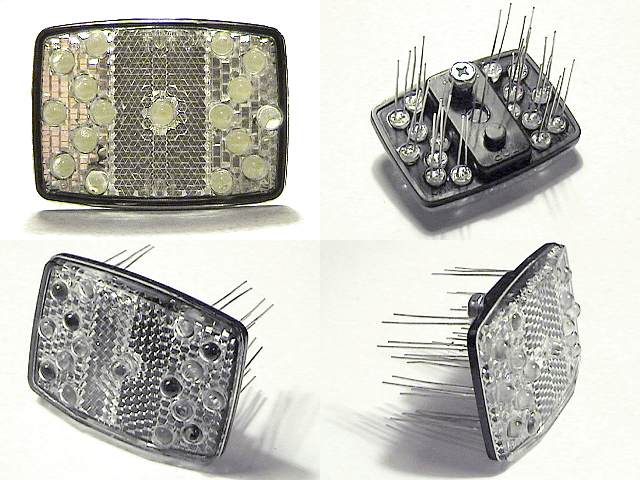
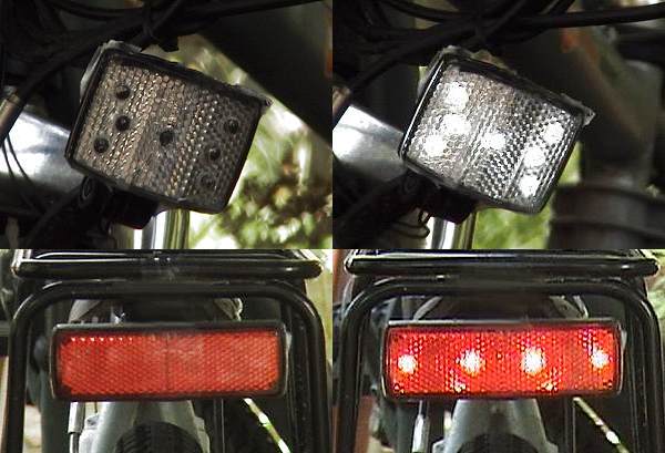
I have added homemade LED lighting to my Urban Mover UM36 which are 'stealthily hidden' in the bike's reflectors and power off the bike's battery, without having to alter anything on the bike to tap the power from the battery:


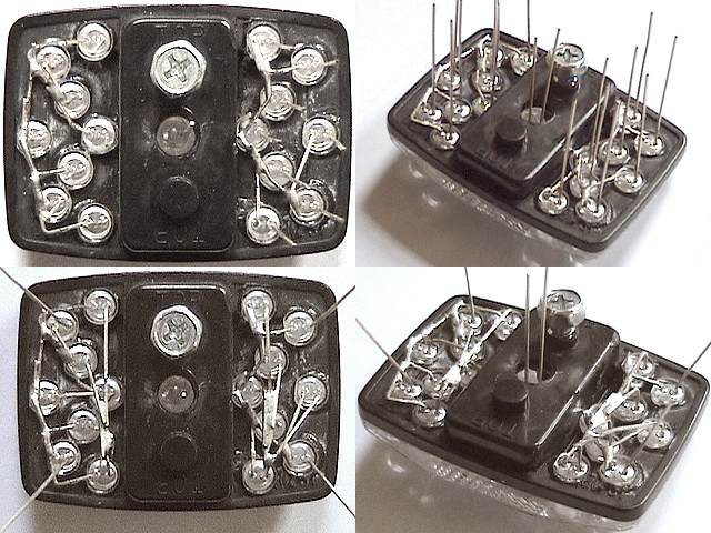
It was easier to do than I first thought so I'm writing up here how I basically do it 'from scratch' because what I have at the moment is working very well but it's a mess of wires, not weatherproof and no on/off switch.

The main advantages of creating your own light setup this way are: you get to decide how bright the lights are, no worries about replacing batteries, no worries about remembering to put the lights on your bike - they're always there, they don't look like traditional lights so the chances of someone stealing them isn't so high (or easy), and as flecc said you don't line the pockets of bike light companies that sell lights more expensive than whole bikes.

Over the next couple of months (just a guess) I'll be posting pictures, info on what bits I bought from where and how I fit it all together.

Just in case someone follows what I'm doing and makes something break or go bang; DISCLAIMER: This is how I am doing things, any modifications or additions you undertake to your bike you do so entirely at your own risk, I will not be held responsible for others actions.


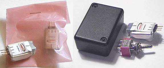
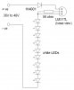
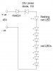
To start the ball rolling I've just ordered two step down adjustable switching regulators for about £16 the pair which can take my bike's 26v battery down to a sustainted voltage anywhere between 1.25v to 13v, which eliminate the need for calculation and use of resistors, the lights won't dim when the battery goes down and I can use a few or a lot of LEDs without doing any complicated wiring or recalculation of resistors values needed.
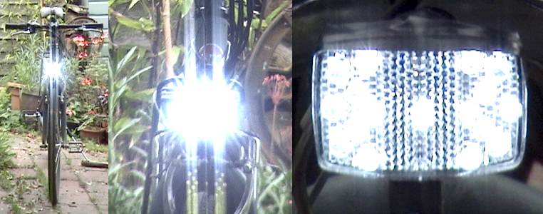
I've also just ordered 30x 55,000mcd 5mm bright white LEDs for about £6 as the 7 ones I'm using now are only 12,000mcd and can light up a dimly lit road and cyclepath ok but I want a BRIGHT front light ;)

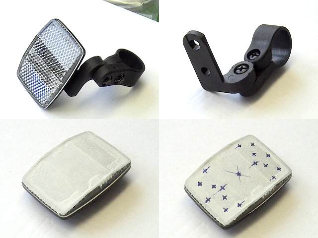
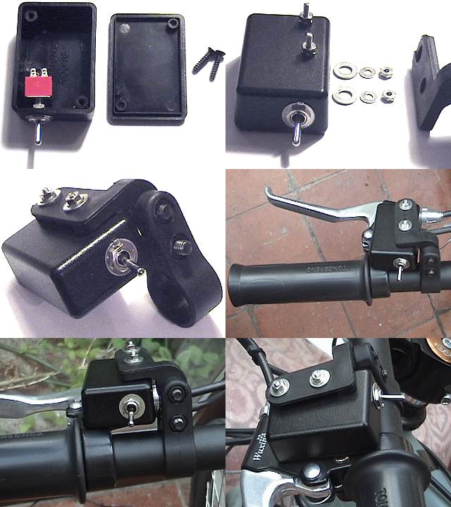
Other bits I already have are; rear reflector, front reflector, super bright Toshiba red LEDs (cost about £1 each from Maplins! but they were leftover from a project years ago, if you need some - eBay), handlebar reflector mount which will be used to hold the box of electronics & on/off switch.


edit: removed link to 55,000mcd LEDs as they're no good for this project, they use 40% more power than these (which are the ones I have used in the prototype and will use in the final) and they aren't 40% brighter.
 
Last edited:

Haku

Esteemed Pedelecer
Jun 20, 2007
339
4
Gloucestershire
Today I got to use a small milling/drilling machine to drill the 5mm sized holes in the front reflector for the LEDs, using such a machine ensures that all the LEDs point in exactly the same direction to give you a spotlight effect.


Using masking tape & a digital micrometer to mark out the spots where I wanted the LEDs I then drilled them, only one LED can be used in the middle of the reflector because of the mounting points (that can be seen on the back images). The masking tape came off in one piece (which was nice). Not all the holes were precicely aligned down to the 1/10 millimeter but that's ok because when the LEDs are installed and switched on you won't be able to notice.

I had to spin the drill at high speed and drill down slowly so the front doesn't crack, my first attempt by just using a hand drill cracked the front in half but being glued to the black back it didn't fall apart.
 
Last edited:

Haku

Esteemed Pedelecer
Jun 20, 2007
339
4
Gloucestershire
Today I received the Adjustable Step Down Regulators, I'll only need one for this project but it's such a useful device I bought a spare, they can take up to 30v input so fine for 24-26v batteries but unfortunately no good for 36v battery setups. But the nice thing about using one of those DC-DC converters for your LED setup is you don't have to use your bike battery, you can easily use a 6 or 8 cell battery pack instead without having to re-calibrate the voltage going to the LEDs as the DC-DC converter outputs the same voltage for the LEDs no matter what the input - so long as it's higher than the voltage used for the LEDs plus 1.3v, so powering 3.4v LEDs you need a minium of 4.7v input.
Another good reason (besides simpler wiring for the LEDs) for using this DC-DC converter is that your lights will remain the same brightness when your bike's battery runs low, I ran mine completely flat recently to help cycle the individual cells inside (battery's running better now), my prototype front light setup remained bright even when the battery could hardly power the motor.

The small black box I'm using to house the switch and the DC-DC unit is from Maplins, part number N78BQ, it's not rated as waterproof but running it under the tap didn't show any leaks, I had to completely submerge it in water and shake/tap it before a couple of drops got in - so I'd say it will be fine for rainy conditions with a little extra care when making it. It will be mounted on the handlebars with the mounting that came off the reflector as my bike already has a reflector mount that goes on the forks.

The switch is also from Maplins, it's a Sub-Min Toggle E as I had it already but the A type is all that's needed, I'll be getting a waterproof cover for it when I can next get over to the store.

 
Last edited:

Haku

Esteemed Pedelecer
Jun 20, 2007
339
4
Gloucestershire
The last heavy downpour a weeks ago ruined the LEDs in my prototype back light because I hadn't waterproofed it (well it was supposed to be summer, as in sun, sun, more sun and only sun) so I ordered some new bright red LEDs from an eBay seller here. I accidentally ordered 3mm instead of 5mm but they're just as bright so no worries.

I wanted to avoid using resistors as much as possible to make things easier to wire but I can't avoid using them for the red LEDs. The white LEDs are 3.4v max but running them at that level isn't good for them as they can get hot and burn out so I set the DC-DC output to 3.15v, so then to power the 1.9v red LEDs from that 3.15v I'm using a single 68 ohm resistor inline for each of the 4 I'm using.

Here's the whole wiring diagram of the project (simple, isn't it):
 
Last edited:

Haku

Esteemed Pedelecer
Jun 20, 2007
339
4
Gloucestershire
17 LEDs now superglued into the front reflector, I had to drill a 7mm hole in the back plastic for the very middle LED so it would stick out of the front instead of being recessed which would cause problems with the mounting bracket:


Next to do is solder all the LED leads together, which is where I deviate slightly from the wiring diagram above, in the future I might setup the front light so it can have a 'low' and 'high' beam by only powering just 5 or all 17, so to do this I'm going to wire the '+' line of 5 LEDs in a separate circuit, but normally I'd just wire all the '+' legs together (along with all the '-' legs together).
 

Haku

Esteemed Pedelecer
Jun 20, 2007
339
4
Gloucestershire
Small update (no pics this time), I wired up the LEDs in the front reflector and temporarily attached it to my bike, it still needs some proper wire attached to it (having a little difficulty finding just the right type) and also waterproofing.

But holy smokes is it bright! one minor annoyance is that the reflector can be angled up/down but the notches are just a tad off for my liking, I can either point it slightly down which won't dazzle anyone but it doesn't fair too well along unlit roads & cyclepaths, or I can point it directly forwards which works extremely well along unlit roads & cyclepaths, I can see *everything* in front of me (reflective roadsigns glow suprisingly bright even from a distance) but it also means anyone in it's beam can be dazzled.

Could I get into any trouble by having it point directly forward?

I also found I had to turn the voltage down from 3.4v to 3.15v as the LEDs were getting quite warm and a couple showed signs of colour shifting to blue as 3.4v is pushing them to their limits, also the DC-DC regulator gets a little warm so I wouldn't power more than 30 LEDs from it, though 17 really is enough for a front light :)
 

ITSPETEINIT

Esteemed Pedelecer
Dec 11, 2006
492
0
Mere, Wilts
Why not a 'dipped' beam?

.

But holy smokes is it bright! one minor annoyance is that the reflector can be angled up/down but the notches are just a tad off for my liking, I can either point it slightly down which won't dazzle anyone but it doesn't fair too well along unlit roads & cyclepaths, or I can point it directly forwards which works extremely well along unlit roads & cyclepaths, I can see *everything* in front of me (reflective roadsigns glow suprisingly bright even from a distance) but it also means anyone in it's beam can be dazzled.

Could I get into any trouble by having it point directly forward?
I don't know how expensive this was to make, or whether there is enough room for two of these reflector lamps on the front of the bike. If you had two and a toggle switch to switch from one to the other so that they were not both on together, that would solve the problem of dazzle on the one hand and good lighting on the other by 'focusing' each on their particular job requirement.
Very sophisticated.
Regards
Peter
PS giving you full marks out of ten for your 'invention' and quality work, I don't know how I have got the audacity to suggest improvement. ;)
You are going to have a proper 'flight deck' soon.
 

Haku

Esteemed Pedelecer
Jun 20, 2007
339
4
Gloucestershire
I don't want to add more reflectors to the front as I want the whole setup to look like there's no whole setup - hence embedding the LEDs into the reflectors.

The thought of two separate lights, one pointing forward & one pointing down, had crossed my mind but that would mean getting hold of another reflector & somehow fitting it onto the bike so it looked like it was meant to be there and not an added accessory.

Hindsight is such a wonderful thing (why can't someone invent the opposite equivilant? ;) ), because if I'd really thought about it I would have drilled some of the LED holes at a 15degree downward angle so I could have high & low beams through a switch. But, when I wired up the front LEDs I put 5 of them on a separate circuit so they can be turned off/on separately from the other 12 (the center one and 4 on the corners which you can see the legs of in the below picture), which would act as a high/low beam setup with the right switching arrangement (5 shining in your face isn't very bad at all, all 17 is though)

For the moment I've set it up so all 17 will be switched on/off with one switch as there's not enough space inside the plastic box for a 2nd switch and the 3 position switch I do have is no good, it can be easily accidentally switched off with a little knock of the lever.

A couple of pics of the initial LED leg wiring, the ground legs are flattened down and all attached together, the positive legs are bent over a few mm above the ground legs so they're not touching:


The whole lot will be 'encased' by using a glue gun as it'll cover everything and make it hopefully very waterproof, then sprayed or painted black so the light doesn't come out the back.
 

Haku

Esteemed Pedelecer
Jun 20, 2007
339
4
Gloucestershire
Working on how and where to mount the small control box containing the on/off switch and the DC-DC converter I've come up with this solution, using the reflector mount that came with the reflector (there's a different one already on the bike that the reflector light uses) it almost looks like it was designed to be there:


frank9755

Esteemed Pedelecer
May 19, 2007
1,228
2
London
Haku,

Your light set-up looks really good; I'd like to have something similar myself!

Have you connected it to your bike's battery, or have you gone for a separate battery box? If the former, how did you do it?

Regards,

Frank
 

Haku

Esteemed Pedelecer
Jun 20, 2007
339
4
Gloucestershire
I started off by powering the few LEDs in the front/back with a 4x AA pack (alkalines lasted much longer than rechargables - a voltage thing) connected to a DC-DC converter, then after a lot of thinking about how to tap the power from the bike's battery I hit upon a solution that wouldn't invalidate the warranty by having to dismantle anythnig, and it was really simple.

My Urban Mover battery has two counter-sunk contacts on it's base which press down on two heavy duty sprung loaded 7mm or so width pins. I made a couple of springs with a width slightly smaller than the contact pins (and soldered wire onto them), so when you twist them onto the contact pins they grip tight.
The great thing is the springs don't get in the way of the battery or the contacts, inbetween the battery base and the bike is a gap of 3mm or so which is enough to bring the wire out without it getting squashed, and it can all be removed very quickly and easily if need be. I'll add a picture of the setup to this post tomorrow.


I'm this close to acquiring all the bits to finish, just need a single 15ohm resistor for the back LEDs (wiring diagram & details in posts will be altered accordingly when fitted as this is all still a work in progress).
 
Last edited:

Haku

Esteemed Pedelecer
Jun 20, 2007
339
4
Gloucestershire
Got problems with the LEDs :(

One of the white LEDs has died and another is flickering, indicating it's going to die. Somewhat fed up because it means I'm going to have to rip them out and replace them, not an easy job when they're superglued in and the legs are soldered to the other LEDs.

I think problem is they're being overdriven, their specs say 3.0v to 3.4v, I've been running them at 3.15v and they get a bit warm, indicating they're getting more power than they can handle so I've set the DC-DC regulator down to 3.0v output and also setup a small experiment - running 6 LEDs on a breadboard being powered with another DC-DC converter at 3.0v for a week non-stop to see how they cope.
 
Last edited:

Haku

Esteemed Pedelecer
Jun 20, 2007
339
4
Gloucestershire
Looks ok for making a fairly foolproof setup, though slightly bulky compared to the Dimension Engineering one, a bit more expensive and not as adjustable.

When doing some eBay searches for Luxeon's I found this listing: Step up - down voltage regulator which looks like an ideal chip to power lights off *any* ebike battery because it can take up to 48v input, however extra components must be needed to make it work properly and that's a little out of my terrortory.
 

Jeremy

Esteemed Pedelecer
Oct 25, 2007
1,010
3
Salisbury
This thread has given me the idea to make my own LED lights, so I've spent the last evening playing about. To ensure reliability and longevity for the white LEDs, I've used a proper constant current source. This is dead easy to build, just a single LM317L adjustable voltage regulator IC, a single 56 ohm resistor plus I added a 1N4001 diode to protect the circuit in case I accidentally swap the leads over (!).

I've wired 9 high brightness white LEDs in series (see circuit below) which works OK from 34V to about 55V. For use on lower voltages the circuit can be modified to use series/parallel strings of LEDS, as described in this application note: http://www.onsemi.com/pub/Collateral/AND8109-D.PDF

For the rear light I'm using a flashing LED in series with seven high brightness red LEDs. This needs a constant voltage drive, so I'm playing about with easy and reliable ways to do this. I may post the results back here later.

Jeremy

Edited to add the rear light circuit diagram, which works a treat and is nice and simple. The flashing LED I used is voltage driven, so doesn't need a constant current source. To allow the array to work at 48V I used a zener diode to limit the available voltage - the value of this will need to be changed for a different supply voltage or different number of series LEDs.

Once I've finished gluing all the bits together I'll try and post a picture.
 

Attachments

Last edited:

Grandad

Pedelecer
Mar 16, 2007
97
0
Devon
grandads.googlepages.com
I have been admiring all the work that has gone into making these LED lamps, well done. :)
My expertise may now be out of date :confused: however I have been puzzled by the use of Voltage regulators as LEDs rely on current control for optimum use. Unless there is an internal resistor, an external one (or a current regulator), should be used to limit the current. (IMHO)

See:
Light Emitting Diodes (LEDs)
Powering Light Emitting Diodes (LEDs)

Here is the spec for one range of high output LEDs
 

Jeremy

Esteemed Pedelecer
Oct 25, 2007
1,010
3
Salisbury
Exactly why I opted to use constant current drive for my front light described above. The "voltage regulator" in my circuit is actually used as a constant current source in this configuration (set for 20mA, by the 1.25V reference drop across the resistor).

The rear light is slightly different, as the flashing LED has an integral IC that automatically limits the current, so this string of LEDs can be driven by any suitable voltage. The flashing LED spec gives an operating voltage of 3.5V to 14V. This is increased by the forward voltage drop of each of the series connected LEDs, in this case to about 16V to 26V. The 28V zener diode increases the operating voltage range again to about 44V to 54V, making the unit suitable for my 48V battery.

I believe that the reason the white LEDs showed signs of early failure in the original posters design was because they were not adequately current limited.

Jeremy
 

john

Esteemed Pedelecer
Nov 1, 2007
531
0
Manchester
Now that it is dark on the way home and being inspired by this thread I thought it was time to add some more lighting to my bike.

I'd been looking at LED's for a while but my criteria were:

- I didn't want to spend a lot of money
- I didn't want it to take a lot of time to put together

Taking some of the ideas from this thread, I went home last night and started playing with an MR16 12V LED bulb I got from ULTIMASTORE - Energy Saving Lamps, LED'S, LED recently. I don't know exactly what is in these but they seem to work happily on 12V AC or DC. I measured the current at about 35mA when connected to a 12V battery and then connected it in series with 820 ohm resistor to connect it to my 36V supply. (actually I used 4 820 resistors in series/parallel - if you know what I mean - in order to handle the power )

I cut a piece of galvanized steel and drilled two holes in it. One for the mounting bolt and a larger one for the bulb. This would then be mounted in place of the front reflector. I used a reamer to make the bulb hole big enough and fixed it in with silicone. Leave overnight to dry and connect the wires to the battery. Bob's your uncle. A really bright light for about half a hour's work and a few quid.

I think it should be OK in the rain as the bulb appears to be totally encased in glass.

The bulb consumes about 0.5 w and the resistors waste about 1W. I'm not too happy about the waste but it's not going to affect my range by more than a few yards so what the heck.
 

Advertisers