How to go about diagnostic testing for a kit that will not switch on?

WillT

Finding my (electric) wheels
Oct 5, 2011
19
2
New Zealand
I bought a hub-motor kit a few years ago as a entry to e-bike experience, which was OK but then it just died and I had no useful response from the place where I purchased it from. Now I use a pro connect disc and am generally very happy.

However, since I discovered this forum recently I wondered if I should try to resurrect the old hub-motor kit to sell and find out a bit more how these things actually work and how to determine what is wrong.

The kit itself has no obvious identifying information that I can find (was called pedal4me 285w by the vendor). It is a 24v 10 Ah motor. There was a key switch that I bypassed when the barrel mechanism became fouled and the key no longer worked.

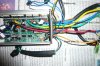
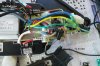
My question is: where do I start in figuring out which component(s) don't work? The lights in the throttle don't come on and the motor doesn't spin. I have a digital multimeter but my electronics knowledge is very rudimentary. Any help or directions to useful resources would be greatly appreciated. I can post some pictures showing the wiring etc coming from the controller, if that would be useful?
 
D

Deleted member 4366

Guest
First check at the two large wires coming out of the controller that you've got 24v or more there. If you have, disconnect the motor and the throttle and check that you have about 5v between the black and the red wires in the throttle connector. I can't see from the photo if there are only 3 wires to the motor, or whether there's an additional connector with 5 thin wires to it. Could you confirm? Is there a pedal sensor in this setup? Answer these questions and do the aove tests and we'll take it from there.

Don't test that your motor spins unless it's clamped in a frame otherwise the axle will spin and rip up all the wires.
 

JuicyBike

Trade Member
Jan 26, 2009
1,671
527
Derbyshire
Remove the brakes and pedal sensor first to reduce the complexity of the setup, then look more closely at the throttle behaviour which sounds the most likely candidate for replacement.
 

WillT

Finding my (electric) wheels
Oct 5, 2011
19
2
New Zealand
Hi d8veh and JuicyBike, many thanks for the guidance. OK - there is about 29v across the big black and red leads that connects the battery (just been charged) to the controller and 4.4v between the black and red wires in the throttle connector. There is indeed a 5-wire connector to the motor (black, red, blue, green yellow) in addition to the 3 thicker wires that go from the controller to the motor (sorry it was a bit hidden in the photo). There are unused wires from the controller, and no pedal sensor or brake sensor connections so no need to worry about those.

So, what next and what do you conclude so far?
 

JuicyBike

Trade Member
Jan 26, 2009
1,671
527
Derbyshire
Voltages all look right. The most vulnerable wires and connectors are those thin wires going to the motor that link to the hall sensors, telling the controller at what angle of rotation the motor is currently. Check those carefully for continuity. There may also be a connector to facilitate rear wheel removal along the cable. Check that also.
 
D

Deleted member 4366

Guest
Hi d8veh and JuicyBike, many thanks for the guidance. OK - there is about 29v across the big black and red leads that connects the battery (just been charged) to the controller and 4.4v between the black and red wires in the throttle connector. There is indeed a 5-wire connector to the motor (black, red, blue, green yellow) in addition to the 3 thicker wires that go from the controller to the motor (sorry it was a bit hidden in the photo). There are unused wires from the controller, and no pedal sensor or brake sensor connections so no need to worry about those.

So, what next and what do you conclude so far?
So far so good. Sorry, I missed the obvious, which needs to be checked next. Most of these controllers have a thin red, orange or pink wire that comes out of the controller near the thick black and red power wires. This thin wire needs to be connected to the battery positive (24 or 36v) to take the controller out of standby mode. The wire is normally routed from the controller through a switch and then on to the battery.

Don't go connecting battery voltage to every pink, orange or red wire on the off-chance because you could damage something. The correct wire needs to be positively identified first. It would help if you could disconnect the controller and lay out all the wires and photograph it so that we can see what you've got.

If that doesn't work, we need to eliminate the throttle as the problem. With it connected, you should still have about 4.4v between the red and the black. Now you need to check between the other wire and the black with it connected. As you open the throttle it should increase from llow to about 4.4v. While you've got your meter out, you could check the hall sensors (the 5 thin wires in a block). There should be about 5v between the red and the black - like the throttle. Then as you rotate the motor, each other wire should switch on and off at about 5v, so check between the black and each colour in turn whilst rotating the motor.

Report back when you've done the tests. Did the motor die while riding it, or just wouldn't start one day?
 
Last edited by a moderator:

WillT

Finding my (electric) wheels
Oct 5, 2011
19
2
New Zealand
Genius - I connected a seemingly loose orange wire to the +ve terminal of the battery and then disconnected it (it normally appeared to just be hanging about disconnected). Then the throttle lights came on and when I connect the motor, hey presto it all works again. So I haven't tested each of the throttle leads that you suggested to do next, since it all seems to work now. I shall put it back on the bike and road test in a few days. Thanks again for your help.
 

JuicyBike

Trade Member
Jan 26, 2009
1,671
527
Derbyshire
d8veh, if you ever need a job... :)
 
D

Deleted member 4366

Guest
I'm probably retiring at Xmas, so if you want to start a shop in Telford and need some part time help, I'd be interested. Most other things I do for free.
 

WillT

Finding my (electric) wheels
Oct 5, 2011
19
2
New Zealand
Don't go connecting battery voltage to every pink, orange or red wire on the off-chance because you could damage something. The correct wire needs to be positively identified first. It would help if you could disconnect the controller and lay out all the wires and photograph it so that we can see what you've got.
Sorry, I just realised that I ignored this piece of advice. I guess I was a bit lucky. I have opened the controller and laid things out as far as I can. Presumably, the orange wire is indeed the reset wire. Can I go ahead and connect this to a switch that goes to +ve battery; then I can reset more easily if this problems happens again?

Thanks so much.
 

Attachments

D

Deleted member 4366

Guest
Sorry, I just realised that I ignored this piece of advice. I guess I was a bit lucky. I have opened the controller and laid things out as far as I can. Presumably, the orange wire is indeed the reset wire. Can I go ahead and connect this to a switch that goes to +ve battery; then I can reset more easily if this problems happens again?

Thanks so much.
It's not a reset wire. Its an "on" wire. When it has battery voltage on it, the controller will give power to the motor. With it disconnected, the controller goes into "standby" mode, so no power. The idea is to connect it to a handlebar switch (sometimes on the throttle body) so that you can switch power on and off while riding the bike - useful for conserving battery or when you're going through a crowded pedestrian area or similar. Another way of achieving the same thing is to leave it permanently connected and then splice a switch into the brake wires because operating the brake switch also effectively puts the controller in "standby" mode, i.e. cuts the power. Finally, you can just leave it permanently connected and forget about standby. It's up to you.
 

WillT

Finding my (electric) wheels
Oct 5, 2011
19
2
New Zealand
Forgive my ignorance, but I am not following this so clearly now. When the orange wire is disconnected, everything still works ie the throttle lights come on and the motor spins. So how come it is an "on" wire? With it connected, everything still works too, but with the switch off (ie the thick red battery +ve wire disconnected from the thick red wire from the controller but the orange wire still connected to voltage), the throttle lights are off except the lowest red light (indicates lowest battery level). So I am a bit confused now.
 
D

Deleted member 4366

Guest
Forgive my ignorance, but I am not following this so clearly now. When the orange wire is disconnected, everything still works ie the throttle lights come on and the motor spins. So how come it is an "on" wire? With it connected, everything still works too, but with the switch off (ie the thick red battery +ve wire disconnected from the thick red wire from the controller but the orange wire still connected to voltage), the throttle lights are off except the lowest red light (indicates lowest battery level). So I am a bit confused now.
Yes. I'm a bit confused now too. I can only tell you what most of these generic Chines controllers are like, but they all have different software. Some have a self-learn mode, where they figure out what type of motor you have and how it's wired. This self-learn mode requires connecting a wire, but I'd be surprised if that's what's happening with yours.

For all my controllers, you should only connect the orange wire when the battery is connected. So, it should be on a switch between your main switch and the controller, so that when you switch off the battery, it goes off too, regardless of its own switch position. That's why your battery light is dim when the main power is off: It's trying to take power through this thin wire instead of the main wire - not to be recommended!
 

JuicyBike

Trade Member
Jan 26, 2009
1,671
527
Derbyshire
Will
Perhaps you have some id on the controller, but as d8veh says, the Chinese are good at standardising with several factories sharing component suppliers. Perhaps the attached schematic would help. Even if the colours are different, you could always use a process of elimination.
 

Attachments

WillT

Finding my (electric) wheels
Oct 5, 2011
19
2
New Zealand
This is very helpful. It looks like the original wiring was wrong. Using the schematic colours (which are roughly the same as my controller), the yellow wire to the throttle was connected straight to the +ve battery lead from the controller and not to the orange wire as illustrated. And in my set-up, the orange wire was not connected to anything. It still worked but I was having problems with it cutting out under load (going up hills) even when the battery had adequate charge. Could the incorrect wiring explain that problem?
 
D

Deleted member 4366

Guest
The yellow wire should be connected to the battery. It gives power to the LEDs, which usually use the throttle ground (black) as its ground. Cutting out wouldn't have been because of the wiring, but instead it's normally caused by a weak battery or its connections.
 

WillT

Finding my (electric) wheels
Oct 5, 2011
19
2
New Zealand
OK, thanks d8veh. Can you tell me how the yellow wire is connected to the battery in the schematic that JuicyBike posted? It looks like the orange wire connects to the yellow wire which connects to the throttle. What am I missing? Cheers.
 

muckymits

Esteemed Pedelecer
May 31, 2011
419
2
just a quick question, how critical is the 5v to the throttle? just I had one the other week on 4.2 volts and only giving 3.5 v back to controller. Manufacturer says it is ok.
 
D

Deleted member 4366

Guest
just a quick question, how critical is the 5v to the throttle? just I had one the other week on 4.2 volts and only giving 3.5 v back to controller. Manufacturer says it is ok.
That sounds about right