How to go about diagnostic testing for a kit that will not switch on?

D

Deleted member 4366

Guest
OK, thanks d8veh. Can you tell me how the yellow wire is connected to the battery in the schematic that JuicyBike posted? It looks like the orange wire connects to the yellow wire which connects to the throttle. What am I missing? Cheers.
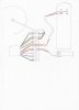
On that schematic, which is a little different to your controller, there's a spare connector from the controller with a battery voltage feed (the red wire) that the yellow wires's connected to. You can connect the yellow wire antwgere you want that has battery voltage, but ideally you want the lights to come on when switched on. I connect mine to controller side of the standby switch so that the lights go off when I put the controller in standby, If you put it the other side of the switch they'll be on all the time the main switch is on, or if you connect it direct to the battery, they'll be on all the time. The LED's use the black throttle wire as the negative, so the throttle needs to be connected for them to work.

The orange wire can connect to the yellow wire because it also normally needs battery voltage. Connecting them together is good because, as I just said, the lights will come on when the controller is active. The fact that you controller still works with the orange wire disconnected is unusual, so I can't say for certain whether it works as described.
 

WillT

Finding my (electric) wheels
Oct 5, 2011
19
2
New Zealand
I think I understand but would like to make quite sure. So I have attached a schematic of my wiring setup in a similar format to JuicyBike's. There are some unused wires from the controller (C, F, G,H) which I won't even ask what they are for.
IMG.jpg
You see that the yellow power wire to the throttle comes straight off the +ve voltage on the controller side of the switch. Also, it seems that there is only one switch (main) unless there is a standby switch somehow in the throttle. So I understand d8veh's advice is to connect the orange wire (F) to the junction of the yellow throttle power wire and the +ve voltage red wire. Have I got this right?

Thanks so much for bearing with me on this.
 

JuicyBike

Trade Member
Jan 26, 2009
1,671
527
Derbyshire
Your schematic is helpful, and shows the throttle receiving 36 Volts. That's bad.
The throttle should receive a 5 volt supply from the controller, not direct from the battery.

I think the yellow from your throttle should go to the orange (F) from your controller.
 
Last edited:
D

Deleted member 4366

Guest
Your schematic is helpful, and shows the throttle receiving 36 Volts. That's bad.
The throttle should receive a 5 volt supply from the controller, not direct from the battery.

I think the yellow from your throttle should go to the orange (F) from your controller.
The yellow is for the LEDs on the throttle not the throttle hall sensor, so, in my view the schematic is correct. Connector C is the pedal sensor and one of the other two is for the brake switch.
 

WillT

Finding my (electric) wheels
Oct 5, 2011
19
2
New Zealand
Well, I guess now I shall have to think a bit and test the alternate configurations that have been recommended. Recall that the setup as illustrated did not actually work (the original reason for my post) until I connected the orange wire (F) to +ve 24v as suggested by d8veh. However (and this is where I am really puzzled), the setup does work now even with the orange wire disconnected again. I will report back what happens with JuicyBike's suggestion. Thanks.
 

JuicyBike

Trade Member
Jan 26, 2009
1,671
527
Derbyshire
Will, I have to point out d8veh's high degree of success in these matters generally and greater experience. If I were completely sure I would say... (I'm not...)
 

WillT

Finding my (electric) wheels
Oct 5, 2011
19
2
New Zealand
We live and learn. d8veh is on the money here - the throttle lights don't glow when the orange wire is just connected to the yellow wire. Clearly the yellow throttle wire needs some voltage. I am still a bit unsure what to do with the orange wire - I don't have a standby switch, so I propose to connect it to the controller side of the main switch (which is connected to the battery). Is that OK?
 
D

Deleted member 4366

Guest
We live and learn. d8veh is on the money here - the throttle lights don't glow when the orange wire is just connected to the yellow wire. Clearly the yellow throttle wire needs some voltage. I am still a bit unsure what to do with the orange wire - I don't have a standby switch, so I propose to connect it to the controller side of the main switch (which is connected to the battery). Is that OK?
That's how many bikes are wired, so shouldn't be a problem. There's still one thing that puzzles me though. Are you absolutely sure that the motor can run without the orange wire connected. If it does, try disconnecting the yellow as well and see if it still runs.
 

WillT

Finding my (electric) wheels
Oct 5, 2011
19
2
New Zealand
Hi dv8veh - the motor will run with the yellow or orange wire (or both) dis-connected, but the throttle lights don't glow without the yellow wire. What does that tell us?