
D
Is my motor ****ed??
- Thread starter Auldgit
- Start date
Hi d8veh, everything I've seen so far appears to be fine. The motor is still noisy and feels rough even when running without the drum, so whatever is causing the problem must be further inside.Did you check the two outer bearings. The one in the photo looks a little rusty.
Cheers AG
Well it seems that the answer to my question is YES! I finally traced the fault to a break in one of the wires going to one of the sensors, caused by the inside of the drum rubbing on it (as suggested by Shemozzle). Put a screwdriver across the break and smooth as you like. Great! However (and this is the sad bit) when attempting to solder a new bit of wire into the gap the wire to the sensor broke off flush with the sensor and is now irreparable.
SO it looks as if I will have to source a new motor. Never mind, a little older and a lot wiser!
Thanks to everyone who contributed.
Cheers AG
SO it looks as if I will have to source a new motor. Never mind, a little older and a lot wiser!
Thanks to everyone who contributed.
Cheers AG
D
Deleted member 4366
Guest
If you look on Endless Sphere, there's tutorials on how to replace a sensor.Well it seems that the answer to my question is YES! I finally traced the fault to a break in one of the wires going to one of the sensors, caused by the inside of the drum rubbing on it (as suggested by Shemozzle). Put a screwdriver across the break and smooth as you like. Great! However (and this is the sad bit) when attempting to solder a new bit of wire into the gap the wire to the sensor broke off flush with the sensor and is now irreparable.
SO it looks as if I will have to source a new motor. Never mind, a little older and a lot wiser!
Thanks to everyone who contributed.
Cheers AG
Sensors are available and cheap , but a bit of a rave to fit ., What have you got to loose by trying ? Or change controller to a no sensor type ?
I am sure you are not going to let this defeat you AG.
You have already shown a lot a engineering skills and determination to get this far.
If you can take a close up photo of the sensor to confirm it is a standard type, all you need to do is make a note of the orientation of the body, which should have a "D" type profile when looking down on the pins, and note which wires go to which pins.
I have a spare I could send you.
It might not be an exact match electrically but I am sure it would get you going again.
You would need to remove carefully the old one then glue the new one in place.
I could solder some flying leads to the new one so you only need to re-terminate the old wires.
I have some thin walled brass tubing which you could use the make the joints if you do not feel you could solder them.
You just feed both wires into opposite ends of the tube and crimp the tube with pliers, making the joint and then slide some heat shrink tubing over it to insulate the connection, which I can also provide.
PM your details if interested.
Last edited:
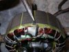
The sensor looks as if it has been slid into the slot and fixed with epoxy resin [Araldite ] Use a small hammer , and the screwdriver in the picture and just tap it out of the slot end . Take care not to damage the windings below it . Sourcing a suitable replacement has been covered inprevious threads and more experienced members will help you source it . Remember that if you use a different brand from an electronics supplier , the pin-outs may be in a different order , and this info will come with the component . As it stands , the motor is scrap , so go for it . You KNOW you want to !
Schemozzle beat me to it .
Schemozzle beat me to it .
Thanks chaps, yes I hate to be beaten but I'm suffering from electric bike fatigue at the moment. I'll sleeep on it and have a closer look tomorrow. Thanks for the offer Shemozzle, I'll probably take you up on it, once if I can get the old one out I can hopefully see what shape it is.
Cheers AG
Cheers AG
D
Deleted member 4366
Guest
If you really want the easy way out, get a sensorless controller like Neptune said - £20 to £25. It'll work perfectly. The KU 63 from BMSbattery can run both with and without sensors.
Thanks for that- another option- I like easy. There's maybe life in the old bike yet. Don't know how my daughter is going to pay the bill for my time though.........If you really want the easy way out, get a sensorless controller like Neptune said - £20 to £25. It'll work perfectly. The KU 63 from BMSbattery can run both with and without sensors.
Cheers AG
Looking at your photo you have a standard hall sensor, so you can replace it.
As an aside, it also shows the cables dressed out using a lacing cord technique a method I thought had been forgotten. It brings back memories of my apprenticeship days making up cable looms back in the early 70's, although I still use it when lashing the dodgers on the side of my friends boat.
As an aside, it also shows the cables dressed out using a lacing cord technique a method I thought had been forgotten. It brings back memories of my apprenticeship days making up cable looms back in the early 70's, although I still use it when lashing the dodgers on the side of my friends boat.
Last edited:
Yes it seemed a bit antique to me I must admit. I remember seeing it on switch panels years ago. I suppose the Chinese have lots of nimble fingered girls to do it, but its use I think may have caused the problem by allowing the loom to be too "high" to clear the rotating drum.Looking at your photo you have a standard hall sensor, so you can replace it.
As an aside, it also shows the cables dressed out using a lacing cord technique a method I thought had been forgotten. It brings back memories of my apprenticeship days making up cable looms back in the early 70's, although I still use it when lashing the dodgers on the side of my friends boat.
Anyway, I've removed the sensor, not too difficult, it is as you say, D shaped, and it measures (looking at the wired end) 1.77mm thick, 4.12mm wide, and (extends into the stator by) 3.19mm deep. Wires are, from left to right, Red, Black, Yellow.
Hope this makes sense. AG
The hall device is just a magnetic switch which is activated by the rotating magnets, it feeds a signal to the controller which in turn fires the power supply to the appropriate main motor winding.
The red and black wires are the supply to the device and the yellow is the output wire to the controller.
I will solder it with the same order of coloured flying leads.
PM you postal address and i'll send out a kit to you.
The red and black wires are the supply to the device and the yellow is the output wire to the controller.
I will solder it with the same order of coloured flying leads.
PM you postal address and i'll send out a kit to you.
Thanks Shemozzle, that's great, will do. AGThe hall device is just a magnetic switch which is activated by the rotating magnets, it feeds a signal to the controller which in turn fires the power supply to the appropriate main motor winding.
The red and black wires are the supply to the device and the yellow is the output wire to the controller.
I will solder it with the same order of coloured flying leads.
PM you postal address and i'll send out a kit to you.
UPDATE: I fitted a new sensor to the motor, bit fiddly but managed it, and it's now running sweetly again. I've waited a while before posting to see whether the problem reappeared but so far so good. Result- SuperDad status restored.
Many thanks to all who advised and helped me, I definitely could not have worked through this one myself.
Cheers AG
Many thanks to all who advised and helped me, I definitely could not have worked through this one myself.
Cheers AG
Related Articles
-
 MTF Enterprises announces acquisition of EMU Electric Bikes
- Started by: Pedelecs
-
 Wisper 806T folding bike wins Which? ‘Best Buy’
- Started by: Pedelecs
-
 Sustrans calls for protected cycle lanes
- Started by: Pedelecs
-
 Amazon launch their first UK e-cargo micromobility hub
- Started by: Pedelecs
