

2J per 0.04secs is 0.08W!you got it wrong. The pulses going through the coils are about 22kHz-40kHz.
the pulse going through the coils lasts only about 0.04ms.
what is the power of 2J delivered in 0.04ms?
It's not the battery that can deliver that power. It's the job for the storage capacitor.
Just bought a used Woosh Fat Boy
- Thread starter MikeFB
- Start date
Very funny.2J per 0.04secs is 0.08W!
You know where I am going with this.
Just to remind ourselves:
Power = energy / time, a 22KHz signal has a wavelength of 1s/22,000 = 0.045ms = 0.000045 second.
If your 48V battery is fully charged, the battery voltage is 53.5V.
Your storage capacitor has 2.2mF capacitance, it stores this much energy:
E = 0.5*V*V*C = 0.5 * 0.0022 * 53.5 * 53.5 = 3.14 Joules
If it was all discharged, the average power in the pulse would be 3.14/0.000045= 70KW.
Of course the average pulse does not have 53.5V amplitude but is still quite considerable.
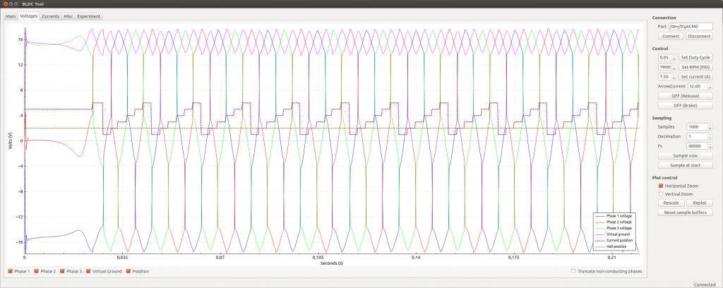
Here is a picture of a very SLOW trace, the motor is on startup where the duty cycle is set to 5%. I chose it because the trace is clean, it illustrates the principle of BLDC motor without suffering back EMF interference.
The capacitor's job isn't to power the motor. It's there to smooth out the battery current. As you rightly say, the demand from the controller is high frequency pulses at an average current of say 17 amps., when going slowly up a hill. To achieve that average, the individual pulses would have to be much higher, which would most likely trip the BMS maximum current, especially at low rpm, where you can hear the individual pulses. The capacitor smooths that out to make a continuous flat demand at 17 amps.
If you look in a range of controllers, you'll see that there's a substantial difference in the size of that/those capacitors. If they drove the motor, you'd have to have different sizes depending on the power you used, but the sizes you see in the controller have no relation to the power output.
If you look in a range of controllers, you'll see that there's a substantial difference in the size of that/those capacitors. If they drove the motor, you'd have to have different sizes depending on the power you used, but the sizes you see in the controller have no relation to the power output.
you need to remember electricity is wave.
If it was flat, the signal across the Atlantic from the earliest telegraph cable (1858) would not have been scrambled.
The early engineers did not undesrtand this, they increased the voltage until the cable burned out.
Now follow the signal along the path from the battery to the coils. The world around us is oscillating in nature. Remember the most fundamental law in the universe: when a particle changes direction, it emits electromagnetic waves.
You must think beyond the simplification of averages.
The easiest way to understand electrical conductivity in an oscillating circuitry is to understand how current flows in a rectilinear aerial.
This is a half wave dipole:

If it was flat, the signal across the Atlantic from the earliest telegraph cable (1858) would not have been scrambled.
The early engineers did not undesrtand this, they increased the voltage until the cable burned out.
Look at the wave forms on the oscilloscope trace. The FET connects directly the coils to your battery. If the wave were flat, how do you explain that trace?The cable functioned for only three weeks, but it was the first such project to yield practical results. The first official telegram to pass between two continents was a letter of congratulations from Queen Victoria of the United Kingdom to President of the United States James Buchanan on August 16. Signal quality declined rapidly, slowing transmission to an almost unusable speed. The cable was destroyed the following month when Wildman Whitehouse applied excessive voltage to it while trying to achieve faster operation.
Now follow the signal along the path from the battery to the coils. The world around us is oscillating in nature. Remember the most fundamental law in the universe: when a particle changes direction, it emits electromagnetic waves.
You must think beyond the simplification of averages.
The easiest way to understand electrical conductivity in an oscillating circuitry is to understand how current flows in a rectilinear aerial.
This is a half wave dipole:
the controller can use the pulse width and frequency modulation to adjust how much power is sent to the motor. As I've shown in the previous post, the duty cycle of that trace was 5%. A 2.2mF capacitor can transmit a lot of power, 1kW is easy peasy. If you need more power, you increase the frequency. A stroboscope is a simple example of high discharge current of a capacitor about 0.1 microfarrad.If they drove the motor, you'd have to have different sizes depending on the power you used, but the sizes you see in the controller have no relation to the power output.
that's a better pictures. You can see clearly how fast the pulses are.
If you can program the controller yourself, you can probably make the motor more flexible without changing the hardware. A bit like the free open source firmware stuff for the TSDZ2.
By the way, I took the Brompton kit for a long-ish ride yesterday. Set the wheel diameter to 16" - maintained 18mph both outbound and inbound. The assistance seems to keep up with my cadence, never hit the treacle. I still have to find an app for GPS test. Quite a few people took an interest at the Brompton. Maybe because I rode it derestricted (on French roads).
Last edited:
All very interesting to us non technical people, but I don't want to go faster, I don't want to go further.
All that I want for my folding hub motor bike is to climb steep hills.
Don't tell me about soldering shunts or even about soldering.
If the manufacturer set the controller just so, obviously it's not meant to give a higher amperage.
All that I want for my folding hub motor bike is to climb steep hills.
Don't tell me about soldering shunts or even about soldering.
If the manufacturer set the controller just so, obviously it's not meant to give a higher amperage.
Hi. The 'significantly sized inductor' is the motor winding itself. I have attached a good educational booklet explaining how these motors behave during pulse width modulation. Page 14 & 15 in particular gives some explanation of how this extra current occurs during the 'diode freewheeling periods'. The controller acts in conjunction with the inductance of the motor. When the mosfet turns off, there is a circuit for the stored induced magnetic energy in the motor coils to continue through the 'body diodes'. This extra current gives extra motor torque and both extra current (in table) and extra torque (in graph) are shown on the motor simulator link I posted earlier and reposted below.Can you explain how the controller is acting like a Buck converter? To do this requires a significantly sized inductor, which I have not seen in any controller I have taken apart.
There is a small Buck converter for the control electronics, but not as far as I am aware for the main drive.
I would like to see an oscilloscope trace of controller output, demonstrating that the controller is actively reducing voltage (other than being unable to supply enough current and having it's voltage pulled down).
Motor Simulator - Tools
Our ebike motor simulator allows you to easily simulate the different performance characteristics of different ebike setups - with a wide selection of hub motors modeled, and the ability to add custom batteries and controllers and set a wide variety of vehicle parameters you'll be able to see...
Attachments
-
1.3 MB Views: 4
Last edited:
Thanks Sturmey, I'll have a read and try and make sense of it. Hopefully you are the "wisest old man" in this particular pubHi. The 'significantly sized inductor' is the motor winding itself. I have attached a good educational booklet explaining how these motors behave during pulse width modulation. Page 14 & 15 in particular gives some explanation of how this extra current occurs during the 'diode freewheeling periods'. The controller acts in conjunction with the inductance of the motor. When the mosfet turns off, there is a circuit for the stored induced magnetic energy in the motor coils to continue through the 'body diodes'. This extra current gives extra motor torque and both extra current (in table) and extra torque (in graph) are shown on the motor simulator link I posted earlier and reposted below.
Motor Simulator - Tools
Our ebike motor simulator allows you to easily simulate the different performance characteristics of different ebike setups - with a wide selection of hub motors modeled, and the ability to add custom batteries and controllers and set a wide variety of vehicle parameters you'll be able to see...www.ebikes.ca

I'm not sure if I'm getting more confused or less after looking at the simulator
If the motor current is vastly different from the battery current, are controllers rated in terms of what they take from the battery rather than they supply to the motor?
What is interesting from the simulator is that when you look at the torque with the higher current controller, it drops off quite quickly well before the 25kph limit, whereas the 48V lower current version still has plenty of torque. So if you set the gradient to 4.5%, no human input, then the 36V system can only sustain 21.5 kph max, whereas the 48V system is still able to sustain 24.6 kph. It looks like there is a sweet spot, where so long as you can sustain more than 20 kph on gradients, the 48V system will perform better in terms of speed between 20 and 25 kph than the 36V system.
This may be why I'm getting good results, I only need PAS setting 1 and it gives nice and smooth acceleration all the way up to 25 kph and on hills around me, climbing is better. On extremely steep hills, according to the simulator, it shouldn't make any difference.
It's worth noting on the site, they don't specify any particular voltage for their motors.
Yes and no. The same controller can be sold to different customers with the current set differently depending on what the customer wants. Some controllers have a range of current that can be set in the settings. It might typically be set to 15 amps, but the setting allows up to 20A. The controller manufacturer wouldn't have put that in if they thought it was going to kill their controller. I heard it's only Apple that does things puts things in their products that kill them, and people are still happy to buy themIf the manufacturer set the controller just so, obviously it's not meant to give a higher amperage.
Apart from that, we have empirical data about what works and what doesn't. It was Fordulike that soldered his whole shunt to get no current limit, and he found that his motor worked, but it got so hot that the hall sensors blew, so we know that you can't run for long with no current limit. I reckon I must have personally soldered at least 50 shunts, and I know of probably another 50 or more other people that have done it. Nobody burnt anything - not one! It's a cost-free method of getting more torque for hill-climbing, and it works on all controllers with a wire shunt that you can get to. People can make any theory they want and get all hysterical to. That's up to them. We practical guys just get on and do it, and live with the inconsequence.
1 ..I think most controllers (on the label) are rated in terms of battery current (often both continuous and maximum). By the way,motor current and battery current are the same once the motor is spinning fast e.g greater than 70%-80% of max speed. Its when the motor start to slow down under load and with pulse width modulation that this changes and motor current increases. That why its important not to bog down motor and why paradoxically increasing battery current (e.g shunt mod) sometimes only slightly increases motor current but can get motor back into the efficiency zone quicker.1....If the motor current is vastly different from the battery current, are controllers rated in terms of what they take from the battery rather than they supply to the motor?
2....... the 48V system will perform better in terms of speed between 20 and 25 kph than the 36V system.
3... they don't specify any particular voltage for their motors.
2..The overvolted 48v system is way ahead of the 36v in terms of speed and especially torque at high speed.( increasing the voltage by 30% also increases the motor rpm by 30%) But here (I think) lies the potential problem, especially for manufacturers and suppliers. The lower voltage setup(lower RPM) will start to self limit at a much lower speed due to motor back emf and this reduces the likelihood of damage, especially by say an overweight and unfit enthusiastic naive user.
3...If you click on 'show advanced', there is an RPM per volt setting. That's because a motor may be used over a range of voltages and its rpm changes proportionally but its rpm/volt does not normally change. You can estimate the rpm/volt of your motor from its unrestricted top speed (wheel off the ground) using simple arithmetic to convert speed to rpm by taking wheel diameter etc. into account and dividing by actual battery voltage.
Last edited:
as it is said in your booklet, the controller is a DC to AC inverter.By the way,motor current and battery current are the same once the motor is spinning fast e.g greater than 70%-80% of max speed. Its when the motor start to slow down under load and with pulse width modulation that this changes and motor current increases. That why its important not to bog down motor and why paradoxically increasing battery current (e.g shunt mod) sometimes only slightly increases motor current but can get motor back into the efficiency zone quicker.
The current in the motor is AC, the current from the battery is DC.
The efficiency of the motor is principally a function whose main variable is the RPM. How can overvolting a 36V controller make the motor more efficient? Would you plug a 12V car inverter into an 18V battery instead of buying the right inverter?
Unfortunately, you are comparing apples and oranges thereas it is said in your booklet, the controller is a DC to AC inverter.
The current in the motor is AC, the current from the battery is DC.
The efficiency of the motor is principally a function whose main variable is the RPM. How can overvolting a 36V controller make the motor more efficient? Would you plug a 12V car inverter into an 18V battery instead of buying the right inverter?
Ok, so you asked, why would anyone want to over volt their bike unless they want to do illegal speeds?
I've been playing with the simulator and hopefully, if I've done this right, it should explain why.
Motor Simulator - Tools
Our ebike motor simulator allows you to easily simulate the different performance characteristics of different ebike setups - with a wide selection of hub motors modeled, and the ability to add custom batteries and controllers and set a wide variety of vehicle parameters you'll be able to see...
This compares a 36V battery and a 59V battery on the same motor.
The controller for 36V is 20A, which is what you would recommend over a standard 15A controller for having more oomph for hill climbing.
The second controller is 59V at 15A, so essentially a 15A "36V" controller over volted to 59V.
When climbing a 4.5% incline, which isn't incredibly steep, the 36V powered system can't even maintain 20kph at 100% throttle.
However, the 59V powered system has no trouble maintaining 25kph at 80% throttle (which is effectively what the limiter will do, throttle the output).
It's using more Watts, but it's well within the tolerable range for these motors and it's likely that the hill will be climbed faster, so putting less stress on the motor as RPMs are higher and it is put under pressure for a shorter time.
In addition, because 100% throttle isn't necessary, efficiency is higher for the 59V system, by about 2%.
Imagine if you are going into a strong headwind, it would have a similar effect. The 36V powered system would not be able to maintain 25kph.
Most controllers labelled as "36V" these days are perfectly capable of running at 48V, or even higher. Also, just swapping to 48V is a modification that doesn't need any shunt soldering or changing other system components, so long as the user is aware of the LVC difference.
For a someone who is a complete novice about this sort of thing, it may not be recommended, but to users who have some knowledge and are well aware of what may or may not happen, I think over volting is a sensible option.
If I've not used the right parameters somewhere, please let me know, but from my experience, this does seem to back up what happens in the real world.
wheezy, you stick a higher voltage to a lightbulb, it will glow brighter but you know already by experience why you wouldn't do that nor would you want to connect that lightbulb to a flat battery.
The argument about motors will run and run because people have all sorts of idea what a BLDC motor is, including those who want to apply Ohm's laws and Kirchoff laws to a circuitry that contains capacitors and coils.
I can go into details formulas and equations but they are of no use here because you don't want formulas and equations.
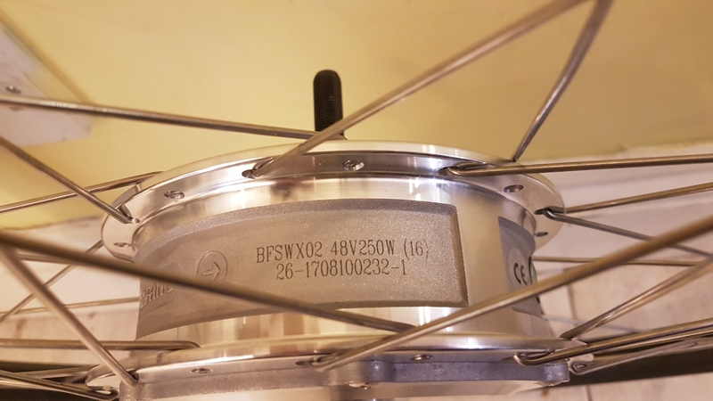
Put simply, I optimise the bike for legal use, 15mph is a known quantity, 36V Lithium Ion battery is also a known quantity. When choosing a motor for a wheel diameter, I can specify the motor winding code. The normal winding code for 36V on 26" wheel is code 13. The normal winding code for 48V on 26" wheel is 16.
If I want to optimise for 20mph, I smply ask for code 16 on 36V, code 12 or 13 on 48V. They are clearly printed on the motor's label by the motor manufacturers. These things are certainly not mystery.
If you want to build your bike for your 52V battery (which requires certification because the nominal DC voltage is more than 48V, electrocution can cause serious injuries) - which motor winding code would you like?
Once you find the answer, you will understand that using the motor outside its optimised voltage is foolish.
edit: my 48V motors have code 16.
If I want to optimise a 48V motor for 20mph, I simply ask for code 13.
The argument about motors will run and run because people have all sorts of idea what a BLDC motor is, including those who want to apply Ohm's laws and Kirchoff laws to a circuitry that contains capacitors and coils.
I can go into details formulas and equations but they are of no use here because you don't want formulas and equations.
Put simply, I optimise the bike for legal use, 15mph is a known quantity, 36V Lithium Ion battery is also a known quantity. When choosing a motor for a wheel diameter, I can specify the motor winding code. The normal winding code for 36V on 26" wheel is code 13. The normal winding code for 48V on 26" wheel is 16.
If you want to build your bike for your 52V battery (which requires certification because the nominal DC voltage is more than 48V, electrocution can cause serious injuries) - which motor winding code would you like?
Once you find the answer, you will understand that using the motor outside its optimised voltage is foolish.
edit: my 48V motors have code 16.
If I want to optimise a 48V motor for 20mph, I simply ask for code 13.
Last edited:
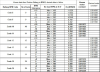
I think you've got your code numbers mixed up. The code number is the number of turns in each coil, so the lower the number, the faster it goes. A code 16 at 36v will barely reach 15 mph, and a code 10 at 48v will do 420 rpm, which is over 30 mph. That's for a 26" wheel.wheezy, you stick a higher voltage to a lightbulb, it will glow brighter but you know already by experience why you wouldn't do that nor would you want to connect that lightbulb to a flat battery.
The argument about motors will run and run because people have all sorts of idea what a BLDC motor is, including those who want to apply Ohm's laws and Kirchoff laws to a circuitry that contains capacitors and coils.
I can go into details formulas and equations but they are of no use here because you don't want formulas and equations.
Put simply, I optimise the bike for legal use, 15mph is a known quantity, 36V Lithium Ion battery is also a known quantity. When choosing a motor for a wheel diameter, I can specify the motor winding code. The normal winding code for 36V on 26" wheel is code 13. The normal winding code for 48V on 26" wheel is 10 or 11.
If I want to optimise for 20mph, I smply ask for code 16 on 36V, code 12 or 13 on 48V. They are clearly printed on the motor's label by the motor manufacturers. These things are certainly not mystery.
If you want to build your bike for your 52V battery (which requires certification because the nominal DC voltage is more than 48V, electrocution can cause serious injuries) - which motor winding code would you like?
Once you find the answer, you will understand that using the motor outside its optimised voltage is foolish.
Good point, but the question is, what is the optimal voltage? If you have a 36v system and you want more speed and torque, the optimal voltage for you is going to be higher than 36v, like 48v.Once you find the answer, you will understand that using the motor outside its optimised voltage is foolish.
I keep saying it, but I'm not sure you understand it, motors don't have a voltage. There's no such thing as a 36v or 48v motor. Instead, motors have a Kv, which is how fast they turn a per volt. The only thing that will burn the motor is current, and you normally use less current at higher voltage for the same power.
Last edited:
agreed.
I re-order the same code times and times again, so easy misquotes.
My 48V motors have code 16.
I re-order the same code times and times again, so easy misquotes.
My 48V motors have code 16.
So from that, can I assume you can't find a problem with the simulation results?wheezy, you stick a higher voltage to a lightbulb, it will glow brighter but you know already by experience why you wouldn't do that nor would you want to connect that lightbulb to a flat battery.
The argument about motors will run and run because people have all sorts of idea what a BLDC motor is, including those who want to apply Ohm's laws and Kirchoff laws to a circuitry that contains capacitors and coils.
I can go into details formulas and equations but they are of no use here because you don't want formulas and equations.
Put simply, I optimise the bike for legal use, 15mph is a known quantity, 36V Lithium Ion battery is also a known quantity. When choosing a motor for a wheel diameter, I can specify the motor winding code. The normal winding code for 36V on 26" wheel is code 13. The normal winding code for 48V on 26" wheel is 10 or 11.
If I want to optimise for 20mph, I smply ask for code 16 on 36V, code 12 or 13 on 48V. They are clearly printed on the motor's label by the motor manufacturers. These things are certainly not mystery.
If you want to build your bike for your 52V battery (which requires certification because the nominal DC voltage is more than 48V, electrocution can cause serious injuries) - which motor winding code would you like?
Once you find the answer, you will understand that using the motor outside its optimised voltage is foolish.
I can understand, as a kit re-seller, you need to cover yourself in case anything goes wrong, so you have to stick with what the manufacturer recommends.
But you can't call people foolish if they are prepared to experiment and investigate something you don't want to look into.
These code numbers are all very well, but go to Grin, they will tell you, voltage "ratings" for motors don't mean all that much.
Optimisation for one set of limited parameters does not mean a perfect solution for all situations.
wheezy, you misunderstand my position.
When you optimise, you consider compromises.
That's why I asked you to select your motor winding for your 52V or 59V battery.
Vfr400 posted the motor winding table for us to use. I use of course the same table because I buy the motors from Bafang themselves.
Choose your motor winding then explain why you choose that one instead of a higher or lower code.
Alternatively, imagine you shop for a 36V kit. The OP's Fat Boy has Bafang G06 code 13.
Which motor winding would you like? Would you like me to supply you with another code?
The argument is the same, if you optimise for one voltage say 36V, it's not going to be as good using a battery higher or lower voltage, 24V or 48V.
Last edited:
now let's consider the financial argument. As I posted earlier, it would cost the OP about £400 for a battery, controller, LCD and wiring loom. In fact, it's the same stuff as in my 48V SWX02 kit minus the motorwheel.
https://wooshbikes.co.uk/cart/#/product/uid-188-swx02-48v12ah/bafang-swx02-48v-250w-rear-hub-kit-with-48v-12ah-battery
I sell the kit for £569 - the wwheel is worth £170, the rest £400. It's a drop in replacement for his Fat Boy.
What would you get for £400?
To me, it does not make economic sense. If it's high speed you want, you would have to derestrict it anyway, 36V or 48V makes no difference.
If it's hill climbing you want, change only the controller for a 25A controller for about £40.
That's why I said the only economic reason for overvolting the Fat Boy to 48V is to ride it at 28mph. At that speed, a £120 direct drive motorwheel is a better choice.
Related Articles
-
 MTF Enterprises announces acquisition of EMU Electric Bikes
- Started by: Pedelecs
-
 Wisper 806T folding bike wins Which? ‘Best Buy’
- Started by: Pedelecs
-
 Sustrans calls for protected cycle lanes
- Started by: Pedelecs
-
 Amazon launch their first UK e-cargo micromobility hub
- Started by: Pedelecs
