

Being my usual bull in a china shop self, I have managed burn out the controller on my wife's urban mover um44sl. I was trying to fit a throttle (on the first day of a week in Derbyshire to enjoy some cycle routes:$). I simply plugged the throttle into the spare connector (it is a throttle specifically for this bike). When I switched the battery on, I got smoke and fizzing from the throttle.
Now the pedelec setting doesn't work. All lights show on the display, there's just no action:-/
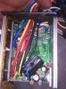
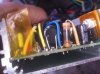
I have had the controller apart, and there is an obviously fried resistor, but I assume that other components are also likely to be jiggered.
Will I be able to repair/replace the controller, and will the throttle be fixable (I don't really want to lash out on another)?
I probably aren't going to be able to sort it for now, due to lack of resources, but I would appreciate some advice for repair/replacement.
Sent from my LT26i using Tapatalk 4
Now the pedelec setting doesn't work. All lights show on the display, there's just no action:-/
I have had the controller apart, and there is an obviously fried resistor, but I assume that other components are also likely to be jiggered.
Will I be able to repair/replace the controller, and will the throttle be fixable (I don't really want to lash out on another)?
I probably aren't going to be able to sort it for now, due to lack of resources, but I would appreciate some advice for repair/replacement.
Sent from my LT26i using Tapatalk 4
Last edited:
 I have indeed managed to send 36v to the throttle. A 4pin connector - 4 wires in, three out. 1 of those in was 36v and I managed to send it to the throttle, thanks to not checking connectivity. There is no response to probes with the multimeter beyond the first capacitor (the big one in the second picture), which seems to be the next component in the circuit from the 36v in. The fried resistor (150 ohm) is showing 200 ohm resistance, presumably as a result of being fried.


