KU63 conundrum...

alban

Pedelecer
May 25, 2011
110
0
OK to save me mucking about please...

Got to find
1. Low V brake switch wire
2. Which 2 wires of speed switch I need to join together permanently to get max speed/ power turned on.

BMSBatt diagram shows out of date connector/wires in these above 2 situations.
I attach 2 poor pics
1. Poss brake switch - yellow, black (not blue) and red connector with a 2 wire connector (yellow, black) coming from it.


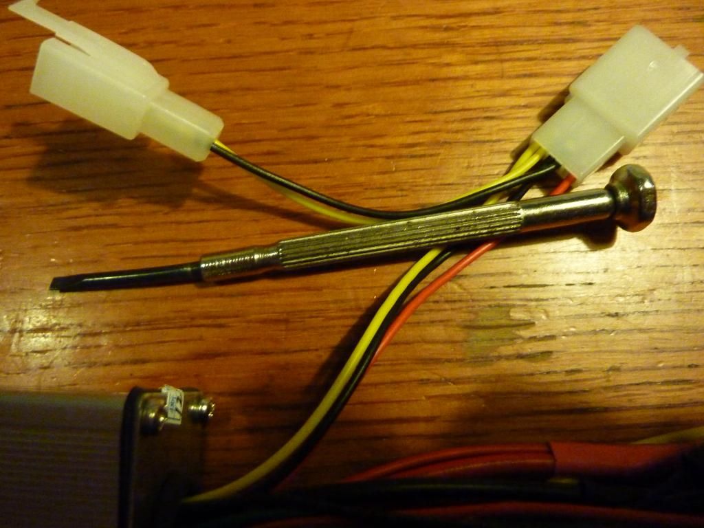
2. SM plug (not white one as in diag) with green, black, blue (and shadow!) Thanks.


Old_Dave

Esteemed Pedelecer
Sep 15, 2012
1,211
2
Dumfries & Galloway
I believe that..

Bottom photo Small black is for magnetic pedelec sensor.

Top photo ... smaller 2 pin plug (yellow and black) is the Low V brake switch

AFAIK the KU63 dosnt have a max speed connection installed
 
D

Deleted member 4366

Guest
Green/black/blue is normally for the three speed switch. The arrangement on the brake connector is so that you can fit the hidden wire brake switches on the three pin connector. Normal brake switches go on the yellow/black. If you want a bit more speed, try joining the black to each of the others in turn. One way it might go slower and the other faster. You need a speedometer on the wheel to check the difference, although sometimes it's obvious because you can see/hear the difference.

The controllers with external speed limit have two white wires. The default is not connected, which means no limit. If you want a speed limit, the connections are still available inside the case. You just have to solder in a bit of wire.
 
Last edited by a moderator:

alban

Pedelecer
May 25, 2011
110
0
OK ta - so just plugging in the yellow wire from the yellow + black 2 pin plug will give me the low V brake switch signal? (There's only one wire connection for brake signal in my Tonaro harness). Got to crimp in a female socket so didn't want to waste any time and effort!
Re the 3 pin speed switch (PAS is the other 3 pin red, green, black SH connector) I just have to experiment with joining blue and then green to black and see which goes faster? - was hoping that it was a known thing!
Yes the KU63s do have the speed limiter 2 white wires but I read that the power is limited across the whole speed range not just after 25KPH so best not to connect them?
6. Disabling speed limit
In the circuit we can see that the speed limit is just a simple voltage divider built with R77 and R87. The motor power of the whole range from 0 to 25kmh is limited instead of just limiting the speed to exact 25kmh. So, better disable the speed limit. The motor controller doesn't measure the bicycle speed. Here I will use a pedelec legalisation device which adds the extra functionality.
KU63 e-bike motor controller

d8veh - do you mean that there is another way of limiting speed to 25KPH inside the box - perhaps without losing power before that speed?

BTW - BMSBatt delivered quickly, straight after Chinese new year - no duty on a small consignment. Couldn't get an answer I understood when asking them for this info tho'. Not really their fault...
 
D

Deleted member 4366

Guest
d8veh - do you mean that there is another way of limiting speed to 25KPH inside the box - perhaps without losing power before that speed?
.
No. If the white wires are missing, you can add your own - is what I was trying to say. As far as I know, the white wires only limit top speed. It has the effect of reducing the throttle signal and the throttle controls speed not power.

With the three speed switch connector, you only have to get a bit of thin wire and use it as a bridge from the middle pin to either of the other two. If it goes faster on one side than without (and that's what you want), you can cut the connector off and join the two wires to keep the higher speed. You'll only see the difference at full throttle.