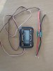
These wattmeters are all over Ebay and Amazon for about £10. They can tell you a lot about how your bike works and everything about your battery if only you could see it while riding. You could thick battery wires up to the hand lebars and back, but not only is that ugly, but you also get some power loss. Here's how to fix all that for almost zero extra cost. All you need is some three-core wire, thinnish, but not too thin - IIRC 22g or thicker is about right; a small piece of vero-board or something similar; a soldering iron; some solder; and a small phillips screwdriver.
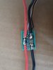
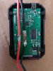
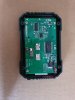
First step unscrew the case. As you can see, it's the same as any of the others. It takes power from the incoming red and black. The red goes straight through. the black goes through an R0001 shunt and out the other side. The current is measured by the voltage drop from one side of the shunt to the other using Ohm's law Current = voltage drop divided by the resistor value. The power in watts are calculated from current times resistance, and the watt-hours are calculated by watts times time. There is a three-pin connector for testing servos, which we don't need. The shunt gets warm at high currents, so they provide ventillation slots at each end of the case:
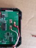
Step 2 unsolder the wires and keep them.
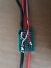
Step 3 unsolder the shunt and cut off that 3-pin connector:
Step 4 solder on the three thin wires. The red goes to where the red wires were soldered, the plack goes to the IN side pad where a black was and the white goes to the other one. Tie a knot or put a zip-tie around the cable to stop it pulling out of the case:
First step unscrew the case. As you can see, it's the same as any of the others. It takes power from the incoming red and black. The red goes straight through. the black goes through an R0001 shunt and out the other side. The current is measured by the voltage drop from one side of the shunt to the other using Ohm's law Current = voltage drop divided by the resistor value. The power in watts are calculated from current times resistance, and the watt-hours are calculated by watts times time. There is a three-pin connector for testing servos, which we don't need. The shunt gets warm at high currents, so they provide ventillation slots at each end of the case:
Step 2 unsolder the wires and keep them.
Step 3 unsolder the shunt and cut off that 3-pin connector:
Step 4 solder on the three thin wires. The red goes to where the red wires were soldered, the plack goes to the IN side pad where a black was and the white goes to the other one. Tie a knot or put a zip-tie around the cable to stop it pulling out of the case:
Last edited: