Been meaning to post this for some time but not got around to it so here goes while I have a moment spare. I think it's worth looking at as the results are quite interesting.
I posted this back in November last year:
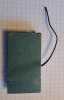
Here is a dismantled Yose power pack, generic Chinese cells, crappy 20A BMS. Bought in 2019, charged only to 41V since June 2020, so 2.5 years of 41V charging, hundreds of cycles and thrashed quite hard, up to 28A cont for many of those cycles. In that time it has never had a charge cycle above 41V.

The BMS has failed after the abuse it has had and I have been planning to replace it for a long time with a better one. So what do the cell bank voltages look like?
Cell Bank / Voltage (V)
1 ............ 3.677
2 ............ 3.678
3 ............ 3.678
4 ............ 3.678
5 ............ 3.677
6 ............ 3.661
7 ............ 3.676
8 ............ 3.678
9 ............ 3.679
10 .......... 3.678
Overall pack voltage 36.762V
So after all that abuse and hundreds of cycles, the maximum variation is 17 mV, mostly because just one bank is slightly lower, the rest are within a couple of mV. I expect the variation to increase slightly once the pack is charged - this is what I find with my homebuilt pack I added monitoring ports to.
I will charge it up with a new BMS and see. However, this variation is unlikely to exceed 20 to 30mV. With this pack I never knew what the bank voltages were from new, so it is quite possible bank 6 has always been like this. I will charge to 41V initially and then to 42V with the new BMS and see what happens to bank 6, will it balance? We'll see.
This quite generic pack was abused and not balanced for 2.5 years and hundreds of cycles and yet it hasn't gone seriously out of balance. This shows that for normal use, charging to 41V for a significant number of cycles, and then balancing at 42V every now and then does not mean a pack's BMS has to be replaced with one designed for 41V charging.
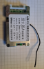
So I connected it up to a new BMS of a similar type to the old one, but with a 30A rating rather than a 20A rating. Then I applied 41V until the voltage did not increase any longer and then the pack was left over the weekend to settle:
Cell Bank / Voltage (V)
1 ............ 4.0924
2 ............ 4.0917
3 ............ 4.0924
4 ............ 4.0922
5 ............ 4.0917
6 ............ 4.0753
7 ............ 4.0909
8 ............ 4.0915
9 ............ 4.0929
10 .......... 4.0920
Overall pack voltage 40.903 V
So by charging to 41V, the maximum difference is still only ~18mV.
The question is, would balancing occur if the charging voltage was increased to 41.5V? Also I was interested to see how much energy was being sacrificed by charging to 41V. So I applied 41.5V to the pack. This consumed 0.9 Ah for this 15Ah pack. Estimating losses during charging, this probably means ~0.7 to 0.8 Ah stored. The pack was allowed to rest and the measured:
Cell Bank / Voltage (V)
1 ............ 4.1417
2 ............ 4.1403
3 ............ 4.1414
4 ............ 4.1413
5 ............ 4.1401
6 ............ 4.1146
7 ............ 4.1384
8 ............ 4.1403
9 ............ 4.1428
10 .......... 4.1411
What is interesting is that the maximum difference has been increased by going above 41V charging to 28.2mV. No sign of any balancing occurring. The next step was to charge to 41.6V. A further 0.156Ah was applied. The voltages were:
Cell Bank / Voltage (V)
1 ............ 4.1625
2 ............ 4.1606
3 ............ 4.1617
4 ............ 4.1617
5 ............ 4.1600
6 ............ 4.1290
7 ............ 4.1582
8 ............ 4.1603
9 ............ 4.1634
10 .......... 4.1613
Overall pack voltage 41.581V
Now the maximum difference has increased to 34.4mV. What is also interesting is that some of the cells are higher than 1/10 of the applied charging voltage of 41.592V. Still no sign of any balancing going on. So next step was 41.7V. This should get interesting as this is the voltage the old Yose Power SANS chargers used to be set to. A further 0.067Ah was applied, so energy input is dropping off.
Cell Bank / Voltage (V)
1 ............ 4.1744
2 ............ 4.1725
3 ............ 4.1736
4 ............ 4.1737
5 ............ 4.1720
6 ............ 4.1381
7 ............ 4.1701
8 ............ 4.1716
9 ............ 4.1731
10 .......... 4.1736
Still no sign of balancing, bank 6 was still low, even after several hours. The current draw from the charger was 0.7 mA, so I left it on over night to see if it would balance by morning:
Cell Bank / Voltage (V)
1 ............ 4.1764
2 ............ 4.1763
3 ............ 4.1757
4 ............ 4.1781
5 ............ 4.1777
6 ............ 4.1416
7 ............ 4.1718
8 ............ 4.1685
9 ............ 4.1763
10 .......... 4.1764
The maximum difference was now 36.5 mV, so no balancing. Hence, the SANS power pack that came with the battery at 41.7 V would not have balanced the battery.
I then tried 41.8V. Something seemed to start happening. The power input went up to 0.183Ah. I disconnected after running for several hours and then on the Monday morning I measured the voltages:
Cell Bank / Voltage (V)
1 ............ 4.1738
2 ............ 4.1766
3 ............ 4.1721
4 ............ 4.1763
5 ............ 4.1791
6 ............ 4.1551
7 ............ 4.1693
8 ............ 4.1658
9 ............ 4.1657
10 .......... 4.1740
Overall pack voltage 41.705V
So the maximum difference has decreased to 24mV. It seems as if some balancing has occurred, but not enough. The next step was to go to 41.9 V. Charging was performed at 41.903V, 0.125Ah was applied. I was monitoring the voltages closely and I was getting a bit concerned about bank 10 as this was over 4.2V per cell.
Cell Bank / Voltage (V)
1 ............ 4.1904
2 ............ 4.1933
3 ............ 4.1888
4 ............ 4.1931
5 ............ 4.1964
6 ............ 4.1837
7 ............ 4.1859
8 ............ 4.1820
9 ............ 4.1822
10 .......... 4.2018
Overall pack voltage 41.898V
Finally, bank 6 is no longer the lowest bank, although the voltage difference between bank 6 and bank 10 is still 18 mV.
I left it charging for several hours then switched it off to rest for a couple of days. I was getting worried as this was pushing one bank over what I was happy with.
Cell Bank / Voltage (V)
1 ............ 4.1741
2 ............ 4.1769
3 ............ 4.1721
4 ............ 4.1767
5 ............ 4.1795
6 ............ 4.1601
7 ............ 4.1664
8 ............ 4.1651
9 ............ 4.1656
10 .......... 4.1744
Overall pack voltage 41.711V
So after relaxing for a while, bank 6 is the lowest value again and the voltage difference is 19.1mV, which is about the same (or a little worse) as what I started with after the pack hadn't been balanced for years.
The things to take away from this exercise:
Balancing did not start until over 4.18V per cell.
There is negligible additional capacity above 4.15V/cell and only about 5 to 6% between 4.1V and 4.15V/cell
The balancing wasn't all that effective compared to no balance at all, the cells seemed to drop back to where they were comfortable after charging. It is also a question how accurately each balancing module in the BMS can measure and hence balance voltage.
It's easy for a good bank to be driven over 4.2V when the BMS tries to balance - even if the overall applied voltage is less than 4.2V/cell, it can't bleed away enough current. The bigger the difference in the banks, the bigger the problem this will be. So if charging to 4.2V every time, the good banks are going to get a lot of stress. If the charger is over 4.2V/cell I imagine the voltage on the best banks will approach harmful levels and drastically shorten life.
It seems to me the best way of making sure a pack stays in balance is to make sure the cells are matched properly in the first place. I think pack manufacturers should print the bank voltages, capacities and internal resistances on the pack when it is new to show that it has been constructed properly.
I posted this back in November last year:
Here is a dismantled Yose power pack, generic Chinese cells, crappy 20A BMS. Bought in 2019, charged only to 41V since June 2020, so 2.5 years of 41V charging, hundreds of cycles and thrashed quite hard, up to 28A cont for many of those cycles. In that time it has never had a charge cycle above 41V.
The BMS has failed after the abuse it has had and I have been planning to replace it for a long time with a better one. So what do the cell bank voltages look like?
Cell Bank / Voltage (V)
1 ............ 3.677
2 ............ 3.678
3 ............ 3.678
4 ............ 3.678
5 ............ 3.677
6 ............ 3.661
7 ............ 3.676
8 ............ 3.678
9 ............ 3.679
10 .......... 3.678
Overall pack voltage 36.762V
So after all that abuse and hundreds of cycles, the maximum variation is 17 mV, mostly because just one bank is slightly lower, the rest are within a couple of mV. I expect the variation to increase slightly once the pack is charged - this is what I find with my homebuilt pack I added monitoring ports to.
I will charge it up with a new BMS and see. However, this variation is unlikely to exceed 20 to 30mV. With this pack I never knew what the bank voltages were from new, so it is quite possible bank 6 has always been like this. I will charge to 41V initially and then to 42V with the new BMS and see what happens to bank 6, will it balance? We'll see.
This quite generic pack was abused and not balanced for 2.5 years and hundreds of cycles and yet it hasn't gone seriously out of balance. This shows that for normal use, charging to 41V for a significant number of cycles, and then balancing at 42V every now and then does not mean a pack's BMS has to be replaced with one designed for 41V charging.
So I connected it up to a new BMS of a similar type to the old one, but with a 30A rating rather than a 20A rating. Then I applied 41V until the voltage did not increase any longer and then the pack was left over the weekend to settle:
Cell Bank / Voltage (V)
1 ............ 4.0924
2 ............ 4.0917
3 ............ 4.0924
4 ............ 4.0922
5 ............ 4.0917
6 ............ 4.0753
7 ............ 4.0909
8 ............ 4.0915
9 ............ 4.0929
10 .......... 4.0920
Overall pack voltage 40.903 V
So by charging to 41V, the maximum difference is still only ~18mV.
The question is, would balancing occur if the charging voltage was increased to 41.5V? Also I was interested to see how much energy was being sacrificed by charging to 41V. So I applied 41.5V to the pack. This consumed 0.9 Ah for this 15Ah pack. Estimating losses during charging, this probably means ~0.7 to 0.8 Ah stored. The pack was allowed to rest and the measured:
Cell Bank / Voltage (V)
1 ............ 4.1417
2 ............ 4.1403
3 ............ 4.1414
4 ............ 4.1413
5 ............ 4.1401
6 ............ 4.1146
7 ............ 4.1384
8 ............ 4.1403
9 ............ 4.1428
10 .......... 4.1411
What is interesting is that the maximum difference has been increased by going above 41V charging to 28.2mV. No sign of any balancing occurring. The next step was to charge to 41.6V. A further 0.156Ah was applied. The voltages were:
Cell Bank / Voltage (V)
1 ............ 4.1625
2 ............ 4.1606
3 ............ 4.1617
4 ............ 4.1617
5 ............ 4.1600
6 ............ 4.1290
7 ............ 4.1582
8 ............ 4.1603
9 ............ 4.1634
10 .......... 4.1613
Overall pack voltage 41.581V
Now the maximum difference has increased to 34.4mV. What is also interesting is that some of the cells are higher than 1/10 of the applied charging voltage of 41.592V. Still no sign of any balancing going on. So next step was 41.7V. This should get interesting as this is the voltage the old Yose Power SANS chargers used to be set to. A further 0.067Ah was applied, so energy input is dropping off.
Cell Bank / Voltage (V)
1 ............ 4.1744
2 ............ 4.1725
3 ............ 4.1736
4 ............ 4.1737
5 ............ 4.1720
6 ............ 4.1381
7 ............ 4.1701
8 ............ 4.1716
9 ............ 4.1731
10 .......... 4.1736
Still no sign of balancing, bank 6 was still low, even after several hours. The current draw from the charger was 0.7 mA, so I left it on over night to see if it would balance by morning:
Cell Bank / Voltage (V)
1 ............ 4.1764
2 ............ 4.1763
3 ............ 4.1757
4 ............ 4.1781
5 ............ 4.1777
6 ............ 4.1416
7 ............ 4.1718
8 ............ 4.1685
9 ............ 4.1763
10 .......... 4.1764
The maximum difference was now 36.5 mV, so no balancing. Hence, the SANS power pack that came with the battery at 41.7 V would not have balanced the battery.
I then tried 41.8V. Something seemed to start happening. The power input went up to 0.183Ah. I disconnected after running for several hours and then on the Monday morning I measured the voltages:
Cell Bank / Voltage (V)
1 ............ 4.1738
2 ............ 4.1766
3 ............ 4.1721
4 ............ 4.1763
5 ............ 4.1791
6 ............ 4.1551
7 ............ 4.1693
8 ............ 4.1658
9 ............ 4.1657
10 .......... 4.1740
Overall pack voltage 41.705V
So the maximum difference has decreased to 24mV. It seems as if some balancing has occurred, but not enough. The next step was to go to 41.9 V. Charging was performed at 41.903V, 0.125Ah was applied. I was monitoring the voltages closely and I was getting a bit concerned about bank 10 as this was over 4.2V per cell.
Cell Bank / Voltage (V)
1 ............ 4.1904
2 ............ 4.1933
3 ............ 4.1888
4 ............ 4.1931
5 ............ 4.1964
6 ............ 4.1837
7 ............ 4.1859
8 ............ 4.1820
9 ............ 4.1822
10 .......... 4.2018
Overall pack voltage 41.898V
Finally, bank 6 is no longer the lowest bank, although the voltage difference between bank 6 and bank 10 is still 18 mV.
I left it charging for several hours then switched it off to rest for a couple of days. I was getting worried as this was pushing one bank over what I was happy with.
Cell Bank / Voltage (V)
1 ............ 4.1741
2 ............ 4.1769
3 ............ 4.1721
4 ............ 4.1767
5 ............ 4.1795
6 ............ 4.1601
7 ............ 4.1664
8 ............ 4.1651
9 ............ 4.1656
10 .......... 4.1744
Overall pack voltage 41.711V
So after relaxing for a while, bank 6 is the lowest value again and the voltage difference is 19.1mV, which is about the same (or a little worse) as what I started with after the pack hadn't been balanced for years.
The things to take away from this exercise:
Balancing did not start until over 4.18V per cell.
There is negligible additional capacity above 4.15V/cell and only about 5 to 6% between 4.1V and 4.15V/cell
The balancing wasn't all that effective compared to no balance at all, the cells seemed to drop back to where they were comfortable after charging. It is also a question how accurately each balancing module in the BMS can measure and hence balance voltage.
It's easy for a good bank to be driven over 4.2V when the BMS tries to balance - even if the overall applied voltage is less than 4.2V/cell, it can't bleed away enough current. The bigger the difference in the banks, the bigger the problem this will be. So if charging to 4.2V every time, the good banks are going to get a lot of stress. If the charger is over 4.2V/cell I imagine the voltage on the best banks will approach harmful levels and drastically shorten life.
It seems to me the best way of making sure a pack stays in balance is to make sure the cells are matched properly in the first place. I think pack manufacturers should print the bank voltages, capacities and internal resistances on the pack when it is new to show that it has been constructed properly.