

Walk assist works, so nothing wrong with motor connections nor the battery nor the controller function.Double check the three phase bullet connectors , it mght be possible that one has been tugged and not giving a correct connection. Bullets are knoe to be troublesome at times , it is also worth gently crimping the female side very slightly to ensure a nice snug tight connection with the male side.
New controller required
- Thread starter pricer592
- Start date
turning the wheel backwards and forwards , all free no resistance ,and rides fine as a normal bike.
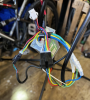
all pins are snug nothing out of place on either side of the 2 black connectors and phase bullets are tight and correctly assembled
on the 4 wire connector i have used my very limited electrical skills and tested the wires individually, the readings are as follows :
Pedal sensor Red and black. 4.7v , Black and blue 3.2 v with or without pedal Black green 3.8 v static variable with pedalling but erratic to 1.9v.
the other black connector with 6 wires is as follows :
Red 4.7v ,Yellow 3.3 v ,Green 0v but 1.7 with walk assist ,Blue 3.3v ,White 3.3 v.
so glad fast jets are easier to work on
To check the pedal sensor, you put the black probe on the black wire and the red probe on the signal wire, then turn the pedals slowly. You should see something around or slightly less than 5v switching on and off approximately 12 times with each rotation with that type of sensor.
Two signal wires is extremely rare. It's 10 years since I've seen that on a pedal sensor. Test both the blue and the green wire to see what's going on. They probably both pulse.
How is your LCD connected because there are no connectors in your photos?
Ebikes are the easiest thing in the world to fix, but nearly impossible from a single picture of a connector or a label on a controller or a number on an LCD. Even worse when people tell you stuff, but not the whole story.
In reply to this I am not sure what your getting at with the above comment of “even worse when people tell you stuff but not the whole story “ you know as much as I do , the connector disengaged whether I caught it and pulled it apart ofr wasn’t properly connected in the first place , I have supplied images which were requested answered all Questions I can , so not really sure what your get at , yes I have tested the wires to the pedal sensor and posted the results on one of my posts and yes one of the wires does as you say voltage jumps around when pedalling the other doesn’tTo check the pedal sensor, you put the black probe on the black wire and the red probe on the signal wire, then turn the pedals slowly. You should see something around or slightly less than 5v switching on and off approximately 12 times with each rotation with that type of sensor.
Two signal wires is extremely rare. It's 10 years since I've seen that on a pedal sensor. Test both the blue and the green wire to see what's going on. They probably both pulse.
How is your LCD connected because there are no connectors in your photos?
Ebikes are the easiest thing in the world to fix, but nearly impossible from a single picture of a connector or a label on a controller or a number on an LCD. Even worse when people tell you stuff, but not the whole story.
Just to add the lcd screen is connected via a multi pin plug which has not been disconnectedTo check the pedal sensor, you put the black probe on the black wire and the red probe on the signal wire, then turn the pedals slowly. You should see something around or slightly less than 5v switching on and off approximately 12 times with each rotation with that type of sensor.
Two signal wires is extremely rare. It's 10 years since I've seen that on a pedal sensor. Test both the blue and the green wire to see what's going on. They probably both pulse.
How is your LCD connected because there are no connectors in your photos?
Ebikes are the easiest thing in the world to fix, but nearly impossible from a single picture of a connector or a label on a controller or a number on an LCD. Even worse when people tell you stuff, but not the whole story.
I can't help you if you don't give precise answers.In reply to this I am not sure what your getting at with the above comment of “even worse when people tell you stuff but not the whole story “ you know as much as I do , the connector disengaged whether I caught it and pulled it apart ofr wasn’t properly connected in the first place , I have supplied images which were requested answered all Questions I can , so not really sure what your get at , yes I have tested the wires to the pedal sensor and posted the results on one of my posts and yes one of the wires does as you say voltage jumps around when pedalling the other doesn’t
What you have to understand is that I've been helping people on this forum for a very long time. When people do the rests I ask and give the results in the way I ask for them, they get sorted in no time.
Unfortunately, it doesn't always work like that. The two most common types of timewasting are: firstly, those that think they know the solution before they ask the question, like "where can I buy a new controller?", when they never tested that there was anything wrong with their controller, and their tu nel vision prevents them from listening to what they'retold; secondly, people that never give the full story, like "My ebike stopped working. Where can I buy a new controller?", then they tell us later that the bike was never working because they bought in that state. Occasionally, though thankfully fairly rare, we get the smart@sses that know the answer before they start. They give minimal info to send us in the wrong direction, then gradually prove that we're wrong by providing just enough info to send us in another wrong direction until they eventually present the answer themselves to show how clever they are.
All some of us want is to make people happy by helping them to fix their bikes, though it becomes a battle of wits as we fight to overcome the obstacles that guys like you put in the way.
OK, with that out the way, let's get back to the battle of wits: Last chance with me. Do the green and blue wires pulse with 5v approximately 12 times per pedal revolution with your meter set to measure volts D/C when you turn the pedal slowly?
Last edited:
Ok I have tested the wires from the pedalI can't help you if you don't give precise answers.
What you have to understand is that I've been helping people on this forum for a very long time. When people do the rests I ask and give the results in the way I ask for them, they get sorted in no time.
Unfortunately, it doesn't always work like that. The two most common types of timewasting are: firstly, those that think they know the solution before they ask the question, like "where can I buy a new controller?", when they never tested that there was anything wrong with their controller, and their tu nel vision prevents them from listening to what they'retold; secondly, people that never give the full story, like "My ebike stopped working. Where can I buy a new controller?", then they tell us later that the bike was never working because they bought in that state. Occasionally, though thankfully fairly rare, we get the smart@sses that know the answer before they start. They give minimal info to send us in the wrong direction, then gradually prove that we're wrong by providing just enough info to send us in another wrong direction until they eventually present the answer themselves to show how clever they are.
All some of us want is to make people happy by helping them to fix their bikes, though it becomes a battle of wits as we fight to overcome the obstacles that guys like you put in the way.
OK, with that out the way, let's get back to the battle of wits: Last chance with me. Do the green and blue wires pulse with 5v approximately 12 times per pedal revolution with your meter set to measure volts D/C when you turn the pedal slowly?
Sensor using the negative from the battery , the results are as follows
Pedal sensor
Red steady . 4.7v
blue 3.2 v with or without pedal turning
green 3.8 v static and variable with pedalling but erratic from 3.8v to 1.9v.
I can make a video to show the multimeter but not sure I can post it on here
As I said before, 4-wire pedal sensors are rare. Yours looks like a 3-wire one, but we can't know how it works without disassembling it. The 4-wire one I had was the conventional open magnet disc and separate sensor. On the surface, it looks like it's not working.
Here's something to try, which might eliminate it from our enquiries. Unplug the pedal sensor. The idea is to mimic the pulse by tapping 5v on a signal wire. Here's how I've rone that. Take a short piece of thin wire or a paperclip; stuff one end up the back of the red wire in the controllerside connector; tap the other end against the pin of the yellow wire. Make sure the wheel is off the ground when you do that because the wheel will spin, hopefully. Repeat for the green wire.
Before any of that, I just noticed that your LCD shows level zero. Please tell me that you tried it on level anything but level zero?
i will go try this now , yes i had just turned it all back on for the picture i have tried on all power setting from 1 to 5 , would it be beneficial to take my crank arm off and open the sensor up for picsAs I said before, 4-wire pedal sensors are rare. Yours looks like a 3-wire one, but we can't know how it works without disassembling it. The 4-wire one I had was the conventional open magnet disc and separate sensor. On the surface, it looks like it's not working.
Here's something to try, which might eliminate it from our enquiries. Unplug the pedal sensor. The idea is to mimic the pulse by tapping 5v on a signal wire. Here's how I've rone that. Take a short piece of thin wire or a paperclip; stuff one end up the back of the red wire in the controllerside connector; tap the other end against the pin of the yellow wire. Make sure the wheel is off the ground when you do that because the wheel will spin, hopefully. Repeat for the green wire.
Before any of that, I just noticed that your LCD shows level zero. Please tell me that you tried it on level anything but level zero?
Just tried what you explained to do with a paper clip no movement at all on either yellow or green wireAs I said before, 4-wire pedal sensors are rare. Yours looks like a 3-wire one, but we can't know how it works without disassembling it. The 4-wire one I had was the conventional open magnet disc and separate sensor. On the surface, it looks like it's not working.
Here's something to try, which might eliminate it from our enquiries. Unplug the pedal sensor. The idea is to mimic the pulse by tapping 5v on a signal wire. Here's how I've rone that. Take a short piece of thin wire or a paperclip; stuff one end up the back of the red wire in the controllerside connector; tap the other end against the pin of the yellow wire. Make sure the wheel is off the ground when you do that because the wheel will spin, hopefully. Repeat for the green wire.
Before any of that, I just noticed that your LCD shows level zero. Please tell me that you tried it on level anything but level zero?
Tested voltages again slowly this time green wire 0 to 3.8v every day 10th of a turn
Blue wire which joins to yellow is a steady 3.29v whether peddling or not .
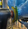
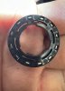
You might be able see something in the pedal sensor right now. Firstly, the inner part doesn't look right. It's no longer flat to the outer. Try turning the pedal to see if the inner part of the sensor goes round with the spindle. If it doesn't, it's jammed, and probably best to take it off, unclip the two halves and clean it out, then reassemble it.Just tried what you explained to do with a paper clip no movement at all on either yellow or green wire
Tested voltages again slowly this time green wire 0 to 3.8v every day 10th of a turn
Blue wire which joins to yellow is a steady 3.29v whether peddling or not .
Ok having looked at the sensor , hope my explanation works , in the picture the red highlighted section is a rubber seal this has always sat a little off the sensor , the yellow bit is the bit that turns it is a small race on the inside which is free to turn by finger , the green inner part seems fixed and part of the bottom bracket I think it’s called , I will take a better picture in the morning of it apart as I didn’t take my phone to the shed this time around , really appreciate your help so far
Attachments
-
 542.9 KB Views: 13
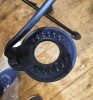
The green and yellow parts clip together and make a housing that encloses the sensor and the magnet disc. You can see the wire coming out the bottom where there are matching lobes on those two parts. I can't see how the yellow part can rotate more than a few degrees relative to the green part because the lobes wouldn't line up.Ok having looked at the sensor , hope my explanation works , in the picture the red highlighted section is a rubber seal this has always sat a little off the sensor , the yellow bit is the bit that turns it is a small race on the inside which is free to turn by finger , the green inner part seems fixed and part of the bottom bracket I think it’s called , I will take a better picture in the morning of it apart as I didn’t take my phone to the shed this time around , really appreciate your help so far
The red part should be tight enough on the pedal spindle that it rotates with it. The magnet disc is attached to the red part inside the yellow and green housing so that the red part and the magnet disc turn inside the housing in front og the hall sensor/s, which is/are located inside that lobe at the bottom. If the red part doesn't turn with the pedals, the magnet disc won't turn either, so the pedal sensor would do nothing.
It's quite common for the magnet disc to jam inside the housing when it gets full of grit. That makes the red part slip on the pedal spindle. The slipping and grit wear the red part so that the hole becomes bigger and it no longer grips even after cleaning out the grit. In that case, you can put a bit of tape around the spindle to tighten the grip.
The green part just clips into the spline in the outer diameter of the bottom bracket. You have to take the pedal off, then wiggle the pedal sensor out as a complete assembly, then you can unclip the green and yellow parts for cleaning.
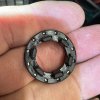
i wasnt too clear on what i meant last night with the yellow part ,my bad , the inner race was turning not the whole sensor , so i have just been and taken the padal off the bike , i took the sensor part off and gave it a clean , all moves freely no gritiness evrything turns as it should when peddaling but still no assist from motor. the voltages remain as the last test with the green wire alternating and yellow wire steady at 3.9vThe green and yellow parts clip together and make a housing that encloses the sensor and the magnet disc. You can see the wire coming out the bottom where there are matching lobes on those two parts. I can't see how the yellow part can rotate more than a few degrees relative to the green part because the lobes wouldn't line up.
The red part should be tight enough on the pedal spindle that it rotates with it. The magnet disc is attached to the red part inside the yellow and green housing so that the red part and the magnet disc turn inside the housing in front og the hall sensor/s, which is/are located inside that lobe at the bottom. If the red part doesn't turn with the pedals, the magnet disc won't turn either, so the pedal sensor would do nothing.
It's quite common for the magnet disc to jam inside the housing when it gets full of grit. That makes the red part slip on the pedal spindle. The slipping and grit wear the red part so that the hole becomes bigger and it no longer grips even after cleaning out the grit. In that case, you can put a bit of tape around the spindle to tighten the grip.
The green part just clips into the spline in the outer diameter of the bottom bracket. You have to take the pedal off, then wiggle the pedal sensor out as a complete assembly, then you can unclip the green and yellow parts for cleaning.
Attachments
-
 314.1 KB Views: 8
 -
 466.1 KB Views: 8
 -
 346.8 KB Views: 8
OK, let's assume that it's working. I bought a couple of kits once that had 4-wire pedal sensors. Upon investigation, one of the wires was not connected inside the controller. Let's also assume that your yellow wire is not connected. You'd have to open the controller and look inside to confirm that. 3.9v is a little low, but should be enough.
That leaves the settings in the LCD as being the culprit. Did you attempt to access the settings to change the wheel size or anything like that?
That leaves the settings in the LCD as being the culprit. Did you attempt to access the settings to change the wheel size or anything like that?