

New controller required
- Thread starter pricer592
- Start date
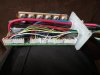
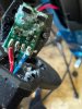
morning , having opened the controller , all wires seem to be in a connected through blocks to the circuit board , nothing appears to be out of place ,and the circuit board itself looks in good condition ,
Attachments
-
 134 KB Views: 12
 -
 113.6 KB Views: 12
That's not a common controller. It's probable that it is using the double hall arrangement for something or other. That leaves two possible causes. Either you changed a setting in the LCD or one of the halls is not working in the sensor, so you must have done something to kill it.morning , having opened the controller , all wires seem to be in a connected through blocks to the circuit board , nothing appears to be out of place ,and the circuit board itself looks in good condition ,
Either way, it won't be easy to find a new controller nor a new pedal sensor. If it were my bike, I'd replace the controller LCD and pedal sensor with ones from KT, and at the same time get a throttle. That would not only solve your problem but it would also give you a much better control system, for about £80. You could also buy a set for about £40-£50 that would work similar to how it's been.
Thank you for your help this far , I followed a video on the tube this morning along the lines of testing the phases of the controller all negative to phase where OL but all positive to phase where in continuity possibly showing a short on the mosfets unsure if that’s what is causing the fault , anyway can you suggest a specific controller to get please
You said your motor works on walk assist!Thank you for your help this far , I followed a video on the tube this morning along the lines of testing the phases of the controller all negative to base where OL but all positive to phase where in continuity, unsure if that’s what is causing the fault , anyway can you suggest a specific controller to get please
Yes that’s correct always works on walk assist , like I say I know sod all about electronics , so following the video on you tube I says it’s the mosfets , I don’t have a clue , think the best way like you say is to swap everything out, can you suggest which model of KT controller to get . I would like the lcd display and a throttle would be great too
If the walk assist works, the controller is working, the motor is working, so is the LCD and the battery. The fault is either that no meaningful signal is coming from the pedal sensor, or the controller settings tell it to ignore the signal.Yes that’s correct always works on walk assist , like I say I know sod all about electronics , so following the video on you tube I says it’s the mosfets , I don’t have a clue , think the best way like you say is to swap everything out, can you suggest which model of KT controller to get . I would like the lcd display and a throttle would be great too
You pedal sensor is not a common one, so we can't be sure how it works, but other 4-wire dual sensor ones pulse on both signal wires (green and yellow). Yours doesn’t, so is probably faulty. The failure mode is very strange because you said it was working, then it mysteriously became disconnected, then didn't work after re-connection. You can't destroy a hall sensor like that, so logic says some part of the story is missing.
The pedal sensor should be fixable. It's mode of operation is very simple: A ring of magnets rotates past two hall sensors. Each time a magnet passes, the magnetic field switches on the path between the 5v leg and the signal leg to make a 5v pulse on each hall sensor. The difference in pulses between the two hall sensors tells the controller which way you'repedalling. It ignores the signals when it sees that you'repedalling backwards.
One of your hall sensors is not making pulses. A simple inspection should show whether there is some reason for that. As always, your photos showed everything but the hall sensors. It's possible that the ground wire or ground leg is broken off if you tugged the cable when it disconnected.
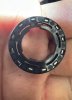
They should sit at the bottom of the housing adjacent to the cable, where the bulge is on the circle. That bulge is to make room for them. Open up the housing again and take some photos of what's down there, and pray that they're not potted with epoxy.Can you explain where that hall sensors are please then I can get a picture of them a so have no idea
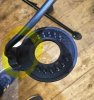
Thanks, I guess by looking at this pic it’s a sealed unit , the magnets clip into the centre and rotate with the pedal , just my luck for it to be sealed , can you suggest a Kt system with a thumb throttle I could buy to swap it all out , might be easier in the long run
Attachments
-
 444.9 KB Views: 7
It may be possible to get some PAS Hall voltage readings via the controller pins outs TA1 & TA2 at the pcb block connector against GND to see if one is faulty.
But yes it is not a commonly use Hall set up and one reason to stay away from even certain hub type bikes that use non std parts.
But yes it is not a commonly use Hall set up and one reason to stay away from even certain hub type bikes that use non std parts.
Doesn't the part you marked in yellow unclip fro the part marked in green?Thanks, I guess by looking at this pic it’s a sealed unit , the magnets clip into the centre and rotate with the pedal , just my luck for it to be sealed , can you suggest a Kt system with a thumb throttle I could buy to swap it all out , might be easier in the long run
I have tested the wires from the pasIt may be possible to get some PAS Hall voltage readings via the controller pins outs TA1 & TA2 at the pcb block connector against GND to see if one is faulty.
But yes it is not a commonly use Hall set up and one reason to stay away from even certain hub type bikes that use non std parts.
red wire has steady 4.7v
Green wire which I imagine is signal wire from hall ranges 0 to 3.2 v which pedal turning slowly
Blue wire which also imagin is a signal wire is steady 3.7 v
On a normal 4 wire system the pedal sensor will have two hall sensors and the position of them relative to each other means there is a phase shift between the pulses on the blue and green wires that the controller interrogates and does its magic to operate the motor.
You aren’t seeing any pulses on the blue wire. But it still doesn’t mean the system is faulty because as it’s a bespoke system we don’t know if it is set up to run with one or two signals.
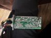
Looking at the markings on the pcb, it’s a Lishui LD-LS01 controller. I don’t know much about these controllers and wasn’t even aware they could accommodate a 4 wire pas.
You aren’t seeing any pulses on the blue wire. But it still doesn’t mean the system is faulty because as it’s a bespoke system we don’t know if it is set up to run with one or two signals.
Looking at the markings on the pcb, it’s a Lishui LD-LS01 controller. I don’t know much about these controllers and wasn’t even aware they could accommodate a 4 wire pas.
Last edited:
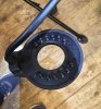
yes the yellow piece comes away from the green piece , picture 1 with the cable , picture 2 clips into the centre of the sensor and ritates on the bottom bracket , seems the sensor is sealed unless the 12 raised bits are the hallsDoesn't the part you marked in yellow unclip fro the part marked in green?
Attachments
-
 314.1 KB Views: 9
 -
 346.8 KB Views: 9
Probably glued together, as the magnet is outside. If you can't open it, it's probably scrap.I don’t think it can be opened it looks like a sealed unit to me , I will check again and take a picture in morning
There is one thing you could try, and that's to put a resistor netween 5k and 10k between the signal wire and the ground to see if it starts switching like the other one. You only need to poke the legs into the connector.

Probably glued together, as the magnet is outside. If you can't open it, it's probably scrap.
There is one thing you could try, and that's to put a resistor netween 5k and 10k between the signal wire and the ground to see if it starts switching like the other one. You only need to poke the legs into the connector.
managed to open the pas , whats inside means nothing to me , i guess the 2 black bits are the hall sensors , is there anyway i can do what you said without a resistor
Attachments
-
 303 KB Views: 17