
That's fair enough. Any safer tests to suggest?Another test that occurred to me could be to get your bike down to say 25% or so and then connect your range extender. Leave it connected for 15 minutes perhaps, and see what the SOC is.
I do not recommend to do that with a DIY extender.
Parallel batteries (again!)
- Thread starter Yak
- Start date

Trying to use logic, this suggests there might a bit of electronic skulduggery going on inside the main in frame battery. If the bike detects another battery then in use it may discharge the second battery hence the thicker discharge wires, however when no discharge is occurring it sets to equalise or charge the inframe battery at 2a hence the thinner wires. Otherwise I see no reason for the thicker set of wires connected to the charge port.. If you take the charge port apart on the gain there are two thick wires and two thin. Perhaps this does relate to an original intention to somehow parallel the extender using the thicker wires with the two thin wires used for the mains charger, but for me, I am simply happy that mine works.
I think I understand. Are you suggesting that the bike's charging system relies on the official accessories (mains charger and range extender) to limit and modulate their output below 2a? and by extension, making more amps available would risk charging the bike battery at a rate higher than 1C. I think this holds if you are working on the hypothesis that the charging port allows a parallel connection to the battery, but I don't think this is confirmed yet? Of course, better safe than sorry.If there was a higher amperage source available, would the system draw it? To answer this just take into consideration that a LiPo cell has a maximum charge capacity ( aprox 3,3 amp/h), so 1C=3,3 Amps/h. The cell could be discharged at a highier rate (more than 1C). But in order to prevent cell destruction, explosion and fire, it should be charged at a rate less than 1C. See cell
specifications attached.
espec
For instance, I am unsure then how the Volabike range extender functions, as those can provide 20amps, unless the ones Volabike has are customised (which is entirely possible).
BTW, I put myself firmly in the "a little knowledge is a dangerous thing" camp and I am not talking from an enlightened position!
That could be similar to how the Bosch system works, swapping from one battery to the other repeatedly, rather than a true parallel connection (which by all accounts sounds dangerous for consumer level tech). ebikemotion may have been aiming for this, but they didn't end up doing it. Their solution for the range extender was to just supply 2 amps to the bike battery as a charger and zero to motor. (according to the orbea range extender manual). I have to wonder why they chose this. It allows you to run out of power, barely touching the range extender, if you ride hard enough! Issues with power delivery, maybe?Trying to use logic, this suggests there might a bit of electronic skulduggery going on inside the main in frame battery. If the bike detects another battery then in use it may discharge the second battery hence the thicker discharge wires, however when no discharge is occurring it sets to equalise or charge the inframe battery at 2a hence the thinner wires. Otherwise I see no reason for the thicker set of wires connected to the charge port.
Although we have conflicting information on this page here, but it seems abandoned: https://www.ebikemotion.com/web/x35-range-extender/ - this says the range extender DOES supply the first 2amps of current to the motor. I suspect this is wrong, but it's not helpful in clearing things up.
I think I understand. Are you suggesting that the bike's charging system relies on the official accessories (mains charger and range extender) to limit and modulate their output below 2a? and by extension, making more amps available would risk charging the bike battery at a rate higher than 1C.I think I understand. Are you suggesting that the bike's charging system relies on the official accessories (mains charger and range extender) to limit and modulate their output below 2a? and by extension, making more amps available would risk charging the bike battery at a rate higher than 1C. I think this holds if you are working on the hypothesis that the charging port allows a parallel connection to the battery, but I don't think this is confirmed yet? Of course, better safe than sorry.
For instance, I am unsure then how the Volabike range extender functions, as those can provide 20amps, unless the ones Volabike has are customised (which is entirely possible).
BTW, I put myself firmly in the "a little knowledge is a dangerous thing" camp and I am not talking from an enlightened position!
Thats my conclusion , for that reason I do not recomend to take any risk.
The DIY extender will work in another approache. I will write some explanation this night. In this DIY process we must be very careful and to follow logical steps always based on what electrical laws dictate.
Really useful work!
Even 2A from the extender is, at 72W or so depending on state of charge, a useful amount of power.
Even 2A from the extender is, at 72W or so depending on state of charge, a useful amount of power.
As Yak has said the charge port has two sets of wires connected, one thin & one thick.
This is highly unusual and the bosh battery sipping system was in my thoughts as well, so this system must be doing something similar when an extender battery is used. It isn't paralleling in the normal proper sense though.
This is highly unusual and the bosh battery sipping system was in my thoughts as well, so this system must be doing something similar when an extender battery is used. It isn't paralleling in the normal proper sense though.
even tho the bosch dual batt system just uses a y cable to connect both batts it is shown on the display that the bike has 2 batts and they use the bms coms to talk to each other and drain as 1 big batt.
now you can get 3rd party batts that will fit bosch gen 2 motors and work but what would happen if you used a bosch batt and a 3rd party one could end up in a big fire lol.
now you can get 3rd party batts that will fit bosch gen 2 motors and work but what would happen if you used a bosch batt and a 3rd party one could end up in a big fire lol.
It will depend on the discharge rate of the main batt. I don not like the idea of stop my ride and wait until main batt get some charge.Really useful work!
Even 2A from the extender is, at 72W or so depending on state of charge, a useful amount of power.
The way I read Yak's comments I have the impression that 2A / 72W is always being taken from the extender, so that if your assistance demand averages less than that, the main battery is not depleted overall at all. It tops up demand above 2A and gets recharged when demand is less than that.It will depend on the discharge rate of the main batt. I don not like the idea of stop my ride and wait until main batt get some charge.
I know from my own experience that I average about 100W assistance, so that my riding style would be met 2/3 by the extender and only 1/3 from the main battery. Effectively that multiplies range by 3, provided the extender is big enough.
As I've mentioned, and this is a very personal conclusion I've come to, the Mahle Battery Extender was designed to function similar to a battery charger with current limiting at 2 amps. Why so? Because it is the safest and easiest way to use by anyone, at any time and without having to take any precautions (plug and play). As the main battery is the one that provides the greatest load demand to the engine, the extender will always go behind the main battery trying to charge it (at times when there is no load demand from the main battery.)
Do they work in parallel? Yes, at times when the motor demands current.
Now let's see what a DIY extender could look like:
1) Like the Mahle, with the main battery charger concept and current limitation always at 2amps.
2) As an additional battery in parallel and with the same current contribution to the load as the main battery. No charger approach.
Why approach 2 is not commonly used? Because it's complicated, risky, and somewhat impractical to use commercially. Not all users would be willing to learn how to use it and it could lead to lawsuits against the manufacturers that market it.
The operating principle of approach 2 is based on the use of 2 battery banks as equal as possible. That is, equal current capacity, equal voltage, equal cell technology. In our case they will be 250Wh 10S2P battery banks. Built from basic Panasonic 18650 cells. One of these banks is just the main battery, the other the extender.
If both batteries are charged to 100% and separately, in theory they will each have the same open circuit voltage. If under these conditions we connect them in parallel, the resulting voltage will be the same and since there is no potential difference between them, there will be no transient current from one battery to the other. The parallel bank will maintain the same voltage while there is no load.
When the motor demands current, that current will be supplied in equal parts by the main and the extender (either high current or low). What happens to the parallel voltage of the bank? Well, go down as current is demanded. One battery charges the other? No. Both batteries are discharged equally until reaching the protection cutoff limit of each of them.
What happens if this procedure is not strictly followed?
I will continue...
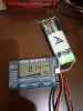
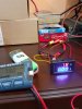
Here are some illustrations of a laboratory scale test. I have used 2 banks 1S 2P of 2550 Ah.
They were separately charged to a certain level and the individual voltages were Bank A = 8.14v, Bank B = 8.13v
connecting both banks in parallel produced a current from A to B of 1.39 mA. Just as expected.
Since there is no load connected to the parallel of batteries, that current is from A charging to B, but as you can see, a load of 1.39 mA to a bank of 2550 mA means that it is charging at a rate of 62x10-3 C. One day it will charged at the same voltage!
I will continue..
Attachments
-
 1.6 MB Views: 10
 -
 1.7 MB Views: 10
 -
 1.8 MB Views: 10
Do they work in parallel? Yes, at times when the motor demands current.As I've mentioned, and this is a very personal conclusion I've come to, the Mahle Battery Extender was designed to function similar to a battery charger with current limiting at 2 amps. Why so? Because it is the safest and easiest way to use by anyone, at any time and without having to take any precautions (plug and play). As the main battery is the one that provides the greatest load demand to the engine, the extender will always go behind the main battery trying to charge it (at times when there is no load demand from the main battery.)
Do they work in parallel? Yes, at times when the motor demands current.
Now let's see what a DIY extender could look like:
1) Like the Mahle, with the main battery charger concept and current limitation always at 2amps.
2) As an additional battery in parallel and with the same current contribution to the load as the main battery. No charger approach.
Why approach 2 is not commonly used? Because it's complicated, risky, and somewhat impractical to use commercially. Not all users would be willing to learn how to use it and it could lead to lawsuits against the manufacturers that market it.
The operating principle of approach 2 is based on the use of 2 battery banks as equal as possible. That is, equal current capacity, equal voltage, equal cell technology. In our case they will be 250Wh 10S2P battery banks. Built from basic Panasonic 18650 cells. One of these banks is just the main battery, the other the extender.
If both batteries are charged to 100% and separately, in theory they will each have the same open circuit voltage. If under these conditions we connect them in parallel, the resulting voltage will be the same and since there is no potential difference between them, there will be no transient current from one battery to the other. The parallel bank will maintain the same voltage while there is no load.
When the motor demands current, that current will be supplied in equal parts by the main and the extender (either high current or low). What happens to the parallel voltage of the bank? Well, go down as current is demanded. One battery charges the other? No. Both batteries are discharged equally until reaching the protection cutoff limit of each of them.
What happens if this procedure is not strictly followed?
I will continue...
The Orbea manual says it only ever gets used as a charger (and is therefore never parallel), but the MAHLE system pdf (for the same device) may suggest something else; in one example up to 2amps are supplied from the range extender to motor, and it charges the bike battery with the remainder (if there is any). In another example, it says 2amps can be supplied to the motor, with the rest coming from the bike battery. Could these be via a parallel connection that is no longer utilised by official kit?
The first example could also explain the existence of two sets of wires, used to power the charging circuit at the same time as supplying current to the motor.
But why the discrepancy between Orbea and MAHLE docs for the same device?
Perhaps they had issues after writing the PDF and the eventual production MAHLE range extender specification changed by the time Orbea became a reseller, and it now uses canbus to keep the system in charging only mode. I agree this sounds like the safest way, if you are not going to do something like the alternating Bosch system for whatever reason.
Devices without canbus then potentially are able to connect to the battery system in parallel and supply more than 2 amps, (in this untested theory, based on a poorly translated PDF which contradicts the mass-produced Orbea manual). Surely they were not considering using an actual electrically parallel battery system? No other manufacturer does that, for good reason!
Or is something else going on.
I'd be interested to know if there's been a reliable demonstration of more than 2amps being supplied to the system through the charging port.
I'd be interested to know if there's been a reliable demonstration of more than 2amps being supplied to the system through the charging port.
A direct current measurement is a bit tricky to do, but using voltage measurements you can come to same conclusions. It is for this reason that Yako's experiment and the voltage measurements that Yako has made, lead to the conclusion that there is consumption of more than 2amps from the DIY extender.
My purpose is to make current measurements directly from the DIY extender through a lab setup and the use of a smart trainer.
But my engineering background makes me go step by step and checking carefully.
Measuring what the extender is doing is relatively straightforward because you have access to the cable. Either one of those cheap wattmeter things wired in, or for isolated measurement, a LEM LTC6 sensor with an arduino or even just a multimeter showing its output.I'd be interested to know if there's been a reliable demonstration of more than 2amps being supplied to the system through the charging port.
A direct current measurement is a bit tricky to do, but using voltage measurements you can come to same conclusions. It is for this reason that Yako's experiment and the voltage measurements that Yako has made, lead to the conclusion that there is consumption of more than 2amps from the DIY extender.
My purpose is to make current measurements directly from the DIY extender through a lab setup and the use of a smart trainer.
But my engineering background makes me go step by step and checking carefully.
Great! Just let us know your measurement results. It will be very valuable for this forum.Measuring what the extender is doing is relatively straightforward because you have access to the cable. Either one of those cheap wattmeter things wired in, or for isolated measurement, a LEM LTC6 sensor with an arduino or even just a multimeter showing its output.
Sorry, I may have not been clear: I measure on my own bikes, and I am operating parallel batteries, and about to add solar charging, but I do not have an Orbea Gain. Just a strong interest in the work being done in this thread.Great! Just let us know your measurement results. It will be very valuable for this forum.
Even if you have measured on other bikes, we can learn the way you did.Sorry, I may have not been clear: I measure on my own bikes, and I am operating parallel batteries, and about to add solar charging, but I do not have an Orbea Gain. Just a strong interest in the work being done in this thread.
If you search for solar trailer you will find my project, and my data will go up there as I collect it.Even if you have measured on other bikes, we can learn the way you did.
Let's go one step further in our model of DIY extender.
We have already seen that we can connect two "same" battery banks in parallel as long as both banks have the same charge. How charge and voltage are related according to the cell manufacturer's curves. So we can say "equal volages = equal charges".
Now, if bank A has a higher charge than bank B, when they are connected in parallel, charges from A will pass to B through an electric current limited only by the internal resistance of the battery banks. these internal resistances are of the order of milliohms and that is why large currents would be caused depending on the level of charge imbalance of bank A and B. Destruction could occur. For this reason, battery chargers limit the maximum current delivered to the load.
Here comes the first alert with the DIY extender.
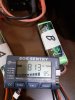
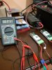
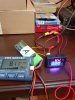
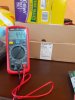
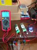
In our lab-scale model, we connected two banks with different charge levels in parallel and measured the current that was produced. See attached figures.
Bank A = 83% charge volt=8.10 v
Bank B = 72% charge volt=7.94 v
Charge imbalance = 15%
At paralleling , I = 44.4 mA from A to B charging rate 0.02C
After some minuts , I = 30.7 mA from A to B charging rate 0.01C
If we let the banks be connect , they will equalize their charges.
One thing you should pay attention to is that the basic cell's voltage curve is almost flat before reaching the point of discharge ( from 4.2v to 3.0v). In the DIY extender and main batt ( from 42v to 30 v).
So small voltage differences between bank A and B can mean large charge differences. Don't forget this point.
I will continue...
We have already seen that we can connect two "same" battery banks in parallel as long as both banks have the same charge. How charge and voltage are related according to the cell manufacturer's curves. So we can say "equal volages = equal charges".
Now, if bank A has a higher charge than bank B, when they are connected in parallel, charges from A will pass to B through an electric current limited only by the internal resistance of the battery banks. these internal resistances are of the order of milliohms and that is why large currents would be caused depending on the level of charge imbalance of bank A and B. Destruction could occur. For this reason, battery chargers limit the maximum current delivered to the load.
Here comes the first alert with the DIY extender.
In our lab-scale model, we connected two banks with different charge levels in parallel and measured the current that was produced. See attached figures.
Bank A = 83% charge volt=8.10 v
Bank B = 72% charge volt=7.94 v
Charge imbalance = 15%
At paralleling , I = 44.4 mA from A to B charging rate 0.02C
After some minuts , I = 30.7 mA from A to B charging rate 0.01C
If we let the banks be connect , they will equalize their charges.
One thing you should pay attention to is that the basic cell's voltage curve is almost flat before reaching the point of discharge ( from 4.2v to 3.0v). In the DIY extender and main batt ( from 42v to 30 v).
So small voltage differences between bank A and B can mean large charge differences. Don't forget this point.
I will continue...
Attachments
-
 1.5 MB Views: 3
 -
 1.4 MB Views: 3
 -
 1.2 MB Views: 3
 -
 1.6 MB Views: 3
Related Articles
-
 MTF Enterprises announces acquisition of EMU Electric Bikes
- Started by: Pedelecs
-
 Wisper 806T folding bike wins Which? ‘Best Buy’
- Started by: Pedelecs
-
 Sustrans calls for protected cycle lanes
- Started by: Pedelecs
-
 Amazon launch their first UK e-cargo micromobility hub
- Started by: Pedelecs
