Red LED on BMS

Blunderbuss

Pedelecer
Mar 11, 2018
158
22
Cambridge
Ouch more on the steep learning curve
It was fine after i did the assembly with the spot welder, it sat around for a week with no change in voltage, but after putting on the BMS and connecting up the main + & - wires last night it seems to have gone a little strange. But at least that should mean i only have to undo the last steps to see what went wrong.

I shall store it in a sand pit for now:D
 

Blunderbuss

Pedelecer
Mar 11, 2018
158
22
Cambridge
I have disconnected the balance wires and the voltage reads 36.2v from the positive on the battery pack to the negative output on the BMS !!!!!

But it now reads 62.1V from the positive to the negative on the battery pack.

Still at room temperate, not hot cells.
 

Blunderbuss

Pedelecer
Mar 11, 2018
158
22
Cambridge
Got home and checked with my DVM (as opposed to the one at work) and it is a steady 54.1V - so that means the work DVM is up the swanny o_O:oops::D

I guess i should have thought about that, still just a couple of wires to solder back on and we will be back on track :cool:
 

awol

Esteemed Pedelecer
Sep 4, 2013
1,216
374
I will give that try - it has "settled" at 73.1V
Looks like your multimeter battery needs changing. They can read incorrect readings with a low battery.
Whats the pink card stuff under the orange tape?
 

Nealh

Esteemed Pedelecer
Aug 7, 2014
20,126
8,225
60
West Sx RH
Phew!!!
At least you double checked with another meter, I have two meters if I have a reading I'm not expecting. I double check and always change the battery to confirm fault.
 

Blunderbuss

Pedelecer
Mar 11, 2018
158
22
Cambridge
Phew!!!
At least you double checked with another meter, I have two meters if I have a reading I'm not expecting. I double check and always change the battery to confirm fault.
I should have guessed sooner that was the problem - else I had found a way to create power from thin air:eek:

Second meter is on order:)
 

Blunderbuss

Pedelecer
Mar 11, 2018
158
22
Cambridge
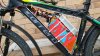
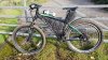
The first battery build is now done, plenty learned on the way. It’s a 14Ah at 48V (13s – 6p) and I took it for the first run today – it performed great :)
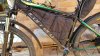
, attached to a 350W bafang geared hub via a 18amp controller. I set the C5 setting at 5 as this gave me 100w on setting 1, 180w on 2 up to 1000w on setting 5 – so plenty of power. I did 25 miles (all offroad) and the voltage dropped from 54.4v to 51.8v which should work out well when winter comes and I am ploughing through the mud. Nothing got hot and with the aluminium frame being held in with additional rivnuts so it is connected to the down tube, seat post and crossbar there were no rattles.

It is just lashed together with cable ties and tape at the moment, and I need to sort out the wiring a bit (basically shorten the various leads so they fit in better). The cover is also lashed up with cable ties, and I have not fitted an on/off switch yet, but I have used XT60’s for the main power connections and XT30s for the lights and USB port.

The spot welder worked a treat and was a million times (for me) easier than soldering the cells.

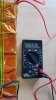
Also I tried this and it worked on three cells that were giving a reading of less than 1v (not using a dodgy DVM :mad:) -

My main lessons learned are:

Check your digital volt meter is working correctly :oops:, and have a spare battery for it.

Don’t use lead free solder, it needs more heat to melt.

Silicon coated wire is great because it is very flexible, but it is much fatter for the same current rating than solid core, so did not fit the BMS.

Forgot that the charging wires from the BMS would need a fitting compatible with my charger – else how was I going to charge it up :rolleyes:.

For the + and – leads that are connected to the first and last cell group I should have soldered the leads to the Nickel strip first and then spot welded the strip it in place. Trying to solder along the Nickel strip that was already spot welded onto the cells took ages and looks a dogs dinner.

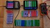
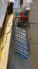
The second build is underway and it will incorporate all the lessons learned (the image shows the cells being tested and sorted) this will take a few weeks to do.

This is an excellent resource if you are using old cells - https://secondlifestorage.com/celldatabase.php

I intend to make three batteries of different capacity that can be fitted in the frame and connected together to give me options for distance vs weight for this bike. But the next project is going to be a Mid Drive (love the Zoobop) or I am seriously tempted by a two wheel drive mud plugger - 250w on the front, 350w on the back run at 52v, 26” wheels in a 27.5” frame with the fattest tyres what will fit :D.
 

Attachments

Blunderbuss

Pedelecer
Mar 11, 2018
158
22
Cambridge
I've now done a good number of runs with the battery and it is doing great, it still charges to 54.4V.

As the mud is building I have gone back to my 26" 500W bafang and squeezed on a 2.6" wide tyre (its a 2.4" wide 27.5" on the front) which is proving to be a really good combination in the mud - but there is a weight penalty, the 500W is heavier and the Hutchinson tyre is 1.4KG, The sidewalls are thick which is noticeable when you are caught in the ruts left by tractors. It provides great grip on the sides without flexing and with the seat post gives a great amount of bump absorbing.

I went over some of the Cambridgeshire "mountain ranges" today and from muddy hollows to hard chalk I did 30 miles and had a voltage of 48.5 left. 20181007_155836.jpg20181007_144931.jpg
 
Last edited: