

There are lots of hidden mists (even big hidden fogs) after the initial ones clear. I suggest you post your proposed order here before actually ordering; one of the experts (not me) may well notice an issue or be able to suggest an improvement.The learning curve mists are clearing and I now have greater confidence of what kit I need and how it should fit together - so will be ordering soon.
Replacing a TranzXPST BL07 battery.
- Thread starter RobT
- Start date
Julet connector systems can be tested but not as straight forward as the sm/block connectors. One has to buy a pair of M/F julet tails of the correct pin out to make up a Y lead that termintes into a block strip, then insert the Y lead between the item to test. Probing the block strip is then easy, just not as convenient or straight forward initially as the older sm connectors.
That looks like a DP15. It's unlikely to work with anything being recommended by others here. If it's in good condition I'd stick that on ebay - you'll likely get £40/50 for it from a Stow-e-way user whose own is knackered (new they're about £100).I have a "supplementary" question regarding keeping the existing Tranz speed/power control and will send with some associated pics soon.
Hi, To all that helped with my queries; I have only very recently got back to the project to restore the Raleigh Pioneer Ebike. So I bought the battery, control box and associated LCD800 display from the guidance you gave. Bit of a challenge to wire it all up, change the connectors etc, but now done and annoyingly the motor/power output from the control box may be faulty.
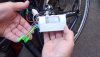
In short, power is getting to the display unit (see pics), however, I believe that a power band should show on the display below the battery level one? …it doesn’t, and the motor does not kick in on cycling. Have rechecked all my connections, all seems as should be BUT, whereas > 41 V showing on display, a multi meter check on the 3 motor output wires from the control box ( again see pic attached) indicates no voltage at any of the 3 pins when the battery and display is powered up. My conclusion is that there must be a fault within the controller box…am I correct, or does the motor only draw power when another, possibly missing signal/sensor reading, tells it to draw power?
Any help welcome, Regards Rob
Attachments
-
 2.5 MB Views: 9
 -
 8 MB Views: 10
You're understanding is incorrect. The motor's three phase wires wires carry a sort of A/C. The controller fires timed pulses ar the motor, but it also checks feedback, so stops if the motor doesn't turn.Hi, To all that helped with my queries; I have only very recently got back to the project to restore the Raleigh Pioneer Ebike. So I bought the battery, control box and associated LCD800 display from the guidance you gave. Bit of a challenge to wire it all up, change the connectors etc, but now done and annoyingly the motor/power output from the control box may be faulty.
In short, power is getting to the display unit (see pics), however, I believe that a power band should show on the display below the battery level one? …it doesn’t, and the motor does not kick in on cycling. Have rechecked all my connections, all seems as should be BUT, whereas > 41 V showing on display, a multi meter check on the 3 motor output wires from the control box ( again see pic attached) indicates no voltage at any of the 3 pins when the battery and display is powered up. My conclusion is that there must be a fault within the controller box…am I correct, or does the motor only draw power when another, possibly missing signal/sensor reading, tells it to draw power?
Any help welcome, Regards Rob
Here's how to test an ebike:
1. Measure the voltage at controller's battery connector. Obviously should be battery voltage. 36v - 42v for a 36v battery would be an acceptable range, but if you've fully charged the battery and it's less than 41v, it needs some sorting.
2. Measure the voltage on the 5v rail. You can measure that between any ground (black) and any of the reds going to throttle, PAS or motor halls. It should be around 5v.
3. Check throttle signal wire voltage on it's connector while connected. it's the wire that's not red or black on the throttle connector. Should give about 1v to 4v when you twist the throttle. If there's more than one wire, your meter will find it. It's the one that's between 1v and 4v, assuming that it works.
4. Check that the pedal assist sensor is pulsing. Measure the PAS signal wire while turning the pedals slowly. Should pulse 5v on and off every time a magnet passes the sensor. The signal wire is the one that's not red or black.
5. Check the motor hall signal wires (blue green and yellow) on the motor connector at the controller. They should each pulse with 5v going on and off as you rotate the wheel BACKWARDS.
6. Mosfet test. Disconnect the motor cable and battery from the controller. Measure the resistance (200k scale) between the red battery connection and each of the three phase wire connections, then repeat with the black battery wire. Each set of 3 readings should be the same as each other and in the range 7K -24K. Though can be higher as long as they're all the same. Due to the capacitor across the battery wire, you can get a constantantly changing measurement while it charges. In that case, try swapping your probes round. Even though can be a moving result, the only important thing is that all three move in a similar way.
To test whether it's working, you should disconnect everything that's not needed, like Pedal sensor, lights and brakes. Listen for a tick or click from the motor when you operate the throttle, which indicates incorrect timing of the power pulses caused by incorrect connection sequence or faulty connection in the motor cable.
If your bike passes all those tests, it should work, so then you can look at any settings or other logical causes, like stuck brake switches, PAS installed backwards.
Many thanks for such a detailed response, however, I sense a potential major issue here, viz: I set out to remediate a (UK) Raleigh Pioneer E-Bike which is EPAC compliant (electric ASSIST and speed limited to 16.6 mph 25 kph)…in particular, it does not have a throttle or brakes related to the motor.You're understanding is incorrect. The motor's three phase wires wires carry a sort of A/C. The controller fires timed pulses ar the motor, but it also checks feedback, so stops if the motor doesn't turn.
Here's how to test an ebike:
1. Measure the voltage at controller's battery connector. Obviously should be battery voltage. 36v - 42v for a 36v battery would be an acceptable range, but if you've fully charged the battery and it's less than 41v, it needs some sorting.
2. Measure the voltage on the 5v rail. You can measure that between any ground (black) and any of the reds going to throttle, PAS or motor halls. It should be around 5v.
3. Check throttle signal wire voltage on it's connector while connected. it's the wire that's not red or black on the throttle connector. Should give about 1v to 4v when you twist the throttle. If there's more than one wire, your meter will find it. It's the one that's between 1v and 4v, assuming that it works.
4. Check that the pedal assist sensor is pulsing. Measure the PAS signal wire while turning the pedals slowly. Should pulse 5v on and off every time a magnet passes the sensor. The signal wire is the one that's not red or black.
5. Check the motor hall signal wires (blue green and yellow) on the motor connector at the controller. They should each pulse with 5v going on and off as you rotate the wheel BACKWARDS.
6. Mosfet test. Disconnect the motor cable and battery from the controller. Measure the resistance (200k scale) between the red battery connection and each of the three phase wire connections, then repeat with the black battery wire. Each set of 3 readings should be the same as each other and in the range 7K -24K. Though can be higher as long as they're all the same. Due to the capacitor across the battery wire, you can get a constantantly changing measurement while it charges. In that case, try swapping your probes round. Even though can be a moving result, the only important thing is that all three move in a similar way.
To test whether it's working, you should disconnect everything that's not needed, like Pedal sensor, lights and brakes. Listen for a tick or click from the motor when you operate the throttle, which indicates incorrect timing of the power pulses caused by incorrect connection sequence or faulty connection in the motor cable.
If your bike passes all those tests, it should work, so then you can look at any settings or other logical causes, like stuck brake switches, PAS installed backwards.
This being so, when I worked through the rather crude wiring diagram provided, I was curious about the throttle and brake wires but, with nothing to connect them to, ignored them. I take it that this particular control box (a Brainpower 800A-6) the throttle control is integral to its function and hence the motor is not kicking in? Is there a work around or do I need to source a different control box and display?
Like most UK EPAC bikes, the Raleigh Pioneer motor reacted to the pedalling sensor to start and then the speed sensor to cut out. Thanks in anticipation of further guidance…and more challenges!
Hi,Every Brainpower controller that I've seen has throttle, pedal sensor and brake connectors. Can you show a link to yours so that we can see what you have instead of a load of tangled and hidden wires?
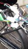
Sure thing, here is what I bought : https://www.ebay.co.uk/itm/226016241668. Attached is the wiring diagram that came with it
Attachments
-
 1.2 MB Views: 14
Did you do the essential self- learning procedure?
If not switch off and connect the green wires. L8ft the wheel off the ground and switch on. After a few seconds the wheel should start twitching then start rotating slowly. If it rotates forward, switch off and disconnect the green wires and never connect them again. If it rotates backwards, indicated by the motor whirring without wheel movement, switch off and repeat from start.
If not switch off and connect the green wires. L8ft the wheel off the ground and switch on. After a few seconds the wheel should start twitching then start rotating slowly. If it rotates forward, switch off and disconnect the green wires and never connect them again. If it rotates backwards, indicated by the motor whirring without wheel movement, switch off and repeat from start.
I have just followed that procedure and the wheel did not rotate, backwards or forwards, neither did the motor make any sound. I presume that the motor isn't getting any power or there is an associated wiring issue - thus I will work through the check list you kindly provided.Did you do the essential self- learning procedure?
If not switch off and connect the green wires. L8ft the wheel off the ground and switch on. After a few seconds the wheel should start twitching then start rotating slowly. If it rotates forward, switch off and disconnect the green wires and never connect them again. If it rotates backwards, indicated by the motor whirring without wheel movement, switch off and repeat from start.
Good news, I appear not to have a dead as a Do Do on my hands; some good progress but more to do, vis: in trying to keep things neat and thus cramming the wiring into the restricted space behind the battery, I appear to have loosened off the +tive bullet connector for the battery - corrected that and found some minor voltages going somewhere by testing red and blacks here and there. In the process, disconnected the 6 pin connector and somehow the front wheel hub motor kicked in; followed the "green" wire test procedure for wheel rotation, also checked the wheel assist levels - all good and now the green wire will be permanently disconnected.
Tests on other wiring functions/links hitherto inconclusive as a problem with the bike stand has stalled tests, however, I did have a brief period of rotating the pedals to check for voltage and motor kicking in whilst rotating the pedals and nothing - so back on to that tomorrow afternoon.
Tests on other wiring functions/links hitherto inconclusive as a problem with the bike stand has stalled tests, however, I did have a brief period of rotating the pedals to check for voltage and motor kicking in whilst rotating the pedals and nothing - so back on to that tomorrow afternoon.
Hi,
I have put some further hours of checks and tests into this and, after some initial encouraging signs, find I have more issues to resolve. Please see attached notes and results of the various wiring tests you kindly provided. I welcome your continued help and further thoughts on the issues. regards
I have put some further hours of checks and tests into this and, after some initial encouraging signs, find I have more issues to resolve. Please see attached notes and results of the various wiring tests you kindly provided. I welcome your continued help and further thoughts on the issues. regards
Attachments
-
 297.1 KB Views: 11
 -
 905.4 KB Views: 13
 -
 951.3 KB Views: 14
 -
 867.1 KB Views: 12
Hello Rob, We’re you able to get it working? If so, what parts are needed? I’m about to attempt the same.