Disclaimer - you mess around with these battery packs at your own risk - what follows are my own observations that may or may not be fact!
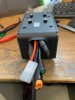
On the yellow connector on the battery: - the two centre connections (O and D shaped) are charging input only. There is circuitry before the actual battery beyond these two pins (measured voltages here don’t reflect the full voltage of the battery pack), so don’t ever try to take output from these, and measuring here with a voltmeter will not give you a true reading of the battery voltage.
In its stand-alone state, the battery will not give any power to the remaining four flat-shaped connections without doing either one of two things. First thing, is pressing the button on the battery itself. The battery charge-state lights will light up, and full battery potential will be presented at the two outermost flat connections of the yellow connector. The second way, is two form a connection between the inner two flat pins. Shorting these two flat pins on the battery will turn the pack on too (I have done this with a wire with a 500mA fuse in it, and it turns the pack on - proven).
So on the bike half of this connector, thats why there are only a red and a black wire coming out of the yellow connector inside the controller box, these wires only connect to the outer two flat pins to feed power to the controller, and the inner two flat pins form a short to turn the battery pack on.
with regard to this shorting link, I tested continuity of the bike connector in both directions to ensure that it wasn’t a diode doing the shorting. There was absolutely no resistance in either direction.