Testing/Fixing Cree T6 battery packs

103Alex1

Esteemed Pedelecer
Sep 29, 2012
2,228
67
I've got a couple of the above 4-cell packs, one of which won't charge for some reason. When I connect it the charger light goes 'red' for a couple of minutes then flicks over to green and charging stops.

It hadn't been used in a while and I plugged it in to top charge up before using it perfectly OK for a run to the shops. When I came back in the dark I switched the light off but forgot to unplug the battery pack. Next day it worked for a couple of minutes then went out (I suspect low voltage) and hasn't charged since. The light is fine as I tested it using my other pack.

Is it possible to test/fix these packs ? I guess the shrinkwrap is going to have to be broken so any ideas of how to get them sealed again if fixed ?

Missing the built-in lighting on my Trek !!!
 

KirstinS

Esteemed Pedelecer
Apr 5, 2011
3,224
899
Brighton
Hi Alex,

I dont have one of these but I belive they are simply 18650 cells inside ?

in which case they can individually tested with a multimeter. Any low voltage cells can be brought back over 3v by using another fully charged 18650 cell and connecting + to + and - to -. For about 10 seconds. Check the cell again and it should be over 3v

This is D8veh's trick and I've used it very succesfully on many 18650 cells taken from laptop packs

Assume these t6 dont have balanceing in them so maybe your cells got out of whack. You could charge each individually using an old phone charge (again a D8veh trick)

Once you have got all back to 4.10v, say, you can reassemble the pack. Unless you use heatshrink I'd probrably go with duct tape and silicon sealant !

I think this should sove issue, if not then one, or more, of the cells may be bad/failing

i
 

Scimitar

Esteemed Pedelecer
Jul 31, 2010
1,772
40
Ireland
Those four-cell packs supplied with those lights have cheap third-rate cells in them, so I'm not too surprised they've given up. Cut your losses and bin them, replacing with something decent and you'll get hundreds of cycles out of them.
 
D

Deleted member 4366

Guest
My theory is that the driver circuit has battery protection, but if you leave them plugged in , but switched off, the driver circuit is still powered, so will flatten the battery completely after 24 hours. Once the cells are under 2v each, the charger wont charge, The same applies if you have the best cells in the world apart from he Ultrafire cells that have their own protection.
 

103Alex1

Esteemed Pedelecer
Sep 29, 2012
2,228
67
Be an interesting exercise if you're able to open the pack up and investigate whether the cells have gone down that far. It was hooked up to the 3-cree light powered off when this happened as the little screw on the QR mount of my 1-cree has perished and I can't get a replacement anywhere local.

The 'having to remember to disconnect the battery pack from the light' issue is one of the things which prompted me to wire in my lighting on the Trek build. It's so easy to forget especially when out on a short trip running the light for only a short time. You know the battery pack doesn't need recharging and this removed the mental trigger to disconnect the battery pack.

I severed the original connector of the light itself in the wheel spokes when I used it in the early Trek testing days... as I'd failed to clock the bars were so much closer to the wheel than on the Agattu ! Cables dangling = caught in wheel !

Rather than re-fit the original rather ropey connector I ordered some of these (which you can take apart and get 2 females and one male connector from) ... and soldered on a much better Magicshine-quality connector to the light. All my CREE lights and both battery packs were made compatible with proper weatherproof connectors and I also used these (or extension leads from same source) inside my Trek box and for the rear light so they're changeable and plug&play :

Buy 5.4mm Male to Dual Female Adapter Y-Cable for SKU 29489/30864 (100cm)

Cheap 5.4mm Male to Female Extension Cable for SKU 29489/30864 (100cm)
 
Last edited:

103Alex1

Esteemed Pedelecer
Sep 29, 2012
2,228
67
Hi Kirstin

Thanks ... I just lost my spare battery pack too so now no packs left at all to run the additional lights on the Agattu up here ! Beginning to think maybe my charger is faulty. When I plugged it in to this pack the red light flickered but didn't stay on. It didn't go back to green either. I don't have a spare charger to test the packs with.

d8veh has my other battery pack and I think is going to test whether the cells are dead when he has the chance.

I'm only here for a couple of days more before going back to Devon - was supposed to have gone back last week but a bunch of stuff came up. Might need to take the lights and pack down there to see if I can do something when I'm back there - as my soldering iron here has packed up now too !

Thankfully my Trek lights in Devon are built-in to run off the bike battery so I'm OK once I get back there for a bit. It's only on the Kalkhoff where I still run them as ancillary.
 

KirstinS

Esteemed Pedelecer
Apr 5, 2011
3,224
899
Brighton
Well just pm me your address if /as/when you need

Might ask for postage costs to be covered though
 

103Alex1

Esteemed Pedelecer
Sep 29, 2012
2,228
67
Thanks Kirstin.

Dave has managed to test the cells and they're fine - seems it's down to weak soldering on a connector strip in the pack which he'll hopefully be able to fix next week. There seems to be a control board with low voltage protection in the shrinkwrapped packs which has likely saved the cells, and they're all showing full charge so looks like my charger is fine too. Just the usual Chinese manufacturing QC issues most likely - plus these packs get velcro-strapped on to the handlebars as I don't have a top tube, so they do bounce around a fair bit. Especially at speed on rough ground. Using cable ties isn't really practical as they have to be removed for charging regularly. So I maybe need to find a way of giving them a bit more protection.

I'm guessing it may well be something similar with my other pack so I'm going to take it down with me and open up / have a go at fixing that too when I get the chance with some tools to hand.
 

103Alex1

Esteemed Pedelecer
Sep 29, 2012
2,228
67
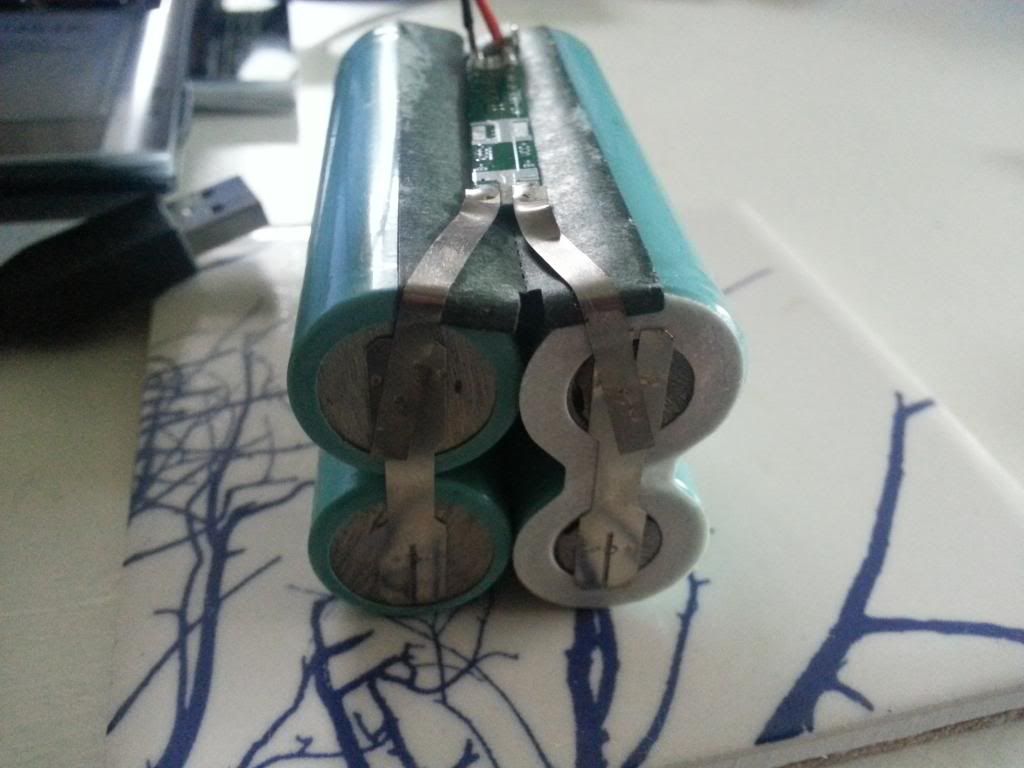
Well, d8veh has kindly fixed the dodgy soldering on 1st pack and it's working fine again. I'm back near my tools now so going to try to test / fix the 2nd pack. Would appreciate some guidance. Here are some photos of the pack opened up ...

- Pack is marked 7.4V / 4400mAh
- individual cells are marked 18650 2200mAh 1207 3.7v.


Putting multimeter across the B+ and B- tabs on the PCB (top photo) gets me 7.81V reading. What next ?
 
Last edited:

103Alex1

Esteemed Pedelecer
Sep 29, 2012
2,228
67
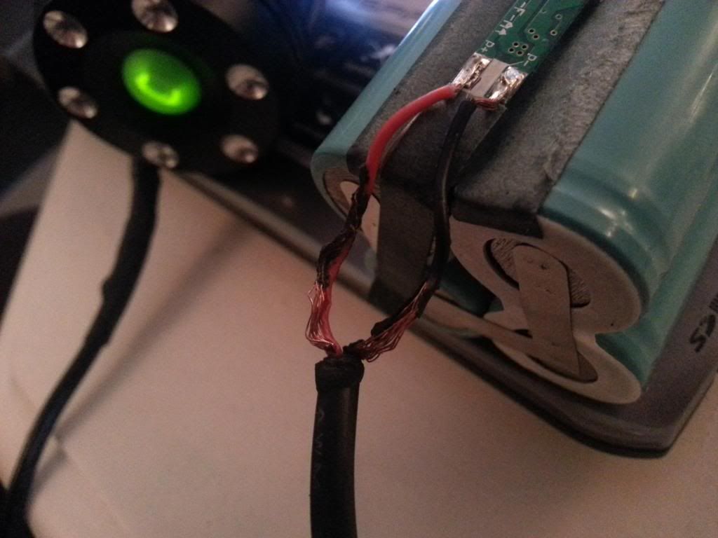
Think I've found the problem .... the inner insulation on the insulated 22AWG wires within the charge receiving / power out lead are badly frayed where they exit the outer insulation leading to the battery PCB P+ / P- contacts. This was at the point where the wiring exited the battery pack shrinkwrap and I'll bet the sharp edge of that shrinkwrap wore away the insulation on the thin inner wires.


After unwrapping and spreading the wires out, the battery pack is powering a 3-CREE light again so the copper inside the black & red inner wires must have been touching and causing a short or triggering some sort of safety cut-off.

Looks like cutting out the bad wiring, resoldering the lead onto the PCB and reinforcing insulation with some shrinkwrap should do the trick. Seems to be nothing wrong with the cells or the BMS/LVC (if there is one).
 
D

Deleted member 4366

Guest
The other pack had a detatched metal strip from the pcb. They join the cells to the pcb. That reminds me: You need to call Ehomer to make arrangements to get your pack back. Have you done it yet?
 

103Alex1

Esteemed Pedelecer
Sep 29, 2012
2,228
67
The other pack had a detatched metal strip from the pcb. They join the cells to the pcb. That reminds me: You need to call Ehomer to make arrangements to get your pack back. Have you done it yet?
Yup - arrived today. Many thanks both.

Btw ... I just recharged the unmended pack and voltage reading 8.05 which doesn't look right. It should be 8.4V I think ?

How do I test voltage of individual cells without shorting anything or blowing myself up ? :)
 
D

Deleted member 4366

Guest
The one I had had three metal strips to the pcb. Depending which pair I measured, I got one cell, the other or both.
 

103Alex1

Esteemed Pedelecer
Sep 29, 2012
2,228
67
The one I had had three metal strips to the pcb. Depending which pair I measured, I got one cell, the other or both.
Perhaps this one is different ? See pics in post 10 ... trying to work out where to actually poke the multimeter pins.

I'm assumin if the individual cells are 3.7V but the pack voltage is twice that then it's effectively 2 strings of 2 cells per string. Is that right ? 1st time I've actually seen inside a battery involving multiple cells so it's complete basics time ... !
 
D

Deleted member 4366

Guest
You photo doesn't go far enough. It needs to show the other end of the PCB where two of the strips were attached on the other pcb. The end facing you is the middle of the pack, and it looks like you can get your probes to the cells, so from end to end on the right is one cell, end to end on the left is the other, and you put your probes left to right on the far end for the pack voltage.
 

103Alex1

Esteemed Pedelecer
Sep 29, 2012
2,228
67
D

Deleted member 4366

Guest
Shame on you. You can see the third strip (middle of the pack) grinning at you from under the black insulation at the wires end. I bet it's connected to that middle pad between the wires.
 

103Alex1

Esteemed Pedelecer
Sep 29, 2012
2,228
67
Shame on you. You can see the third strip (middle of the pack) grinning at you from under the black insulation at the wires end. I bet it's connected to that middle pad between the wires.
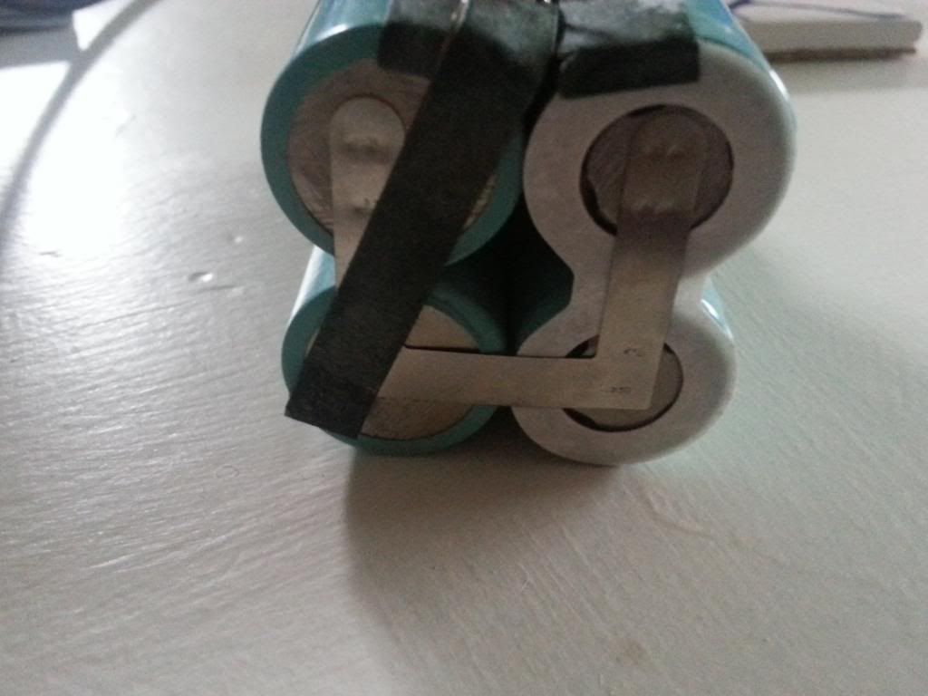
OK a horizontal strip at the bottom of the 3 joined strips forming a U-shaped tab attached to the 4 cells - I still don't understand how it works as far as what is +ve / what is -ve on the horizontal strip or why the tabs are like that.

2 of the cells in a vertical stack under the PCB are facing one way (+ve / -ve orientation) and the other 2 are facing the other way and the vertical strips (with PCB uppermost) bridge the battery pairs together (as if they were one battery of same voltage / double the capacity ?). So logically a horizontal strip on one end (PCB uppermost) between 2 pairs joins a pair of +ve to a pair of -ve with the opposite sides of the battery pairs unbridged. So what does that mean ... and do I have a pair of cells which are out of balance from the readings off the ends of the cells themselves ?
 
D

Deleted member 4366

Guest
Just stick your probes on the ends of any cell. Do it on each cell to get 4 readings, two pairs of which will be the same because the cells are joined.