throttle and PAS connection

Eugenio966

Finding my (electric) wheels
Oct 2, 2017
6
1
57
Italy
Hello,

I ask your kind support for the issue in subject.
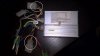
In my ebike controller I found 2 connectors with 3 wires:

1. Yellow, Green and Red
2. Black, Yellow and Red

The first seems a throttle connection as bringing 5V on the Green the motor starts running (Red is a 5V and Yellow is to ground). While does not trigger the motor with the PAS square signal. The Green is terminated to H0 on the PCB.

I need the connection to the PAS. On the other connector I measured, when powered up, 5V on the Red (Black is to ground) and on the Yellow 6V (not stable). The Yellow is terminated to VP on the PCB. Could be this one the connector for the PAS? I was not confident to try and risking to burn the controller...

There is a way to discover it?

In the picture attached the controller and the (2) connectors.

Many thanks!
Eugenio
 

Attachments

Woosh

Trade Member
May 19, 2012
19,529
16,466
Southend on Sea
wooshbikes.co.uk
You confirmed correctly that 1 (Yellow, Green and Red) is the throttle.
The PAS signal needs to be pulsed at least a few times in a second to start the motor.
Check with a multitester that yellow and red on 1 are connected to yellow and red on 2, therefore leaving green (2) as the PAS signal.
 
  • Informative
Reactions: LeighPing

Eugenio966

Finding my (electric) wheels
Oct 2, 2017
6
1
57
Italy
Hi Woosh,

thanks!
Can you please explain a little more the test you are suggesting?
Yellow on 1 is connected to ground and Green is working on Toggle mode.

Eugenio
 

Woosh

Trade Member
May 19, 2012
19,529
16,466
Southend on Sea
wooshbikes.co.uk
Hi Woosh,

thanks!
Can you please explain a little more the test you are suggesting?
Yellow on 1 is connected to ground and Green is working on Toggle mode.

Eugenio
test for continuity between the two connectors 1 and 2. Red to red (4.5V), yellow to yellow (ground). Then you know for certain that the green (2) is the signal. I think you have already confirmed that.

The problem you may encounter is the colours of the wires from the PAS sensor do not match the colours on (2).
If this is the case, post a picture of the connector on the PAS sensor.
There is no simple way to identify which wire is which on the PAS side. However, many of us have come across a few, so we may be able to give you our educated guesses.
 

Eugenio966

Finding my (electric) wheels
Oct 2, 2017
6
1
57
Italy
Hi Woosh,

I have identified the colour with functonality on the PAS.
My corncern is that I could damage the controller if I connect the PAS to connector 2. Yellow cable on connector 2 has 6V once the controller is powered. I'm a little bit worried to bring the yellow to ground once connected to PAS (pulsing from 0 to 5 when pedal is running).
 
D

Deleted member 4366

Guest
It's dead simple. if you have 5v between the red and the black, that connector is for a sensor, so you can connect a PAS to it without any problem. The controller needs an exact pattern from the pulsing to recognise that it's getting the correct forward pedal motion, so tapping the signal wire with 5v pulses probably won't work.

Connect a PAS, then test it by rotating the magnet disc against the sensor. there's two ways up you can orientate the disc and two directions to rotate it, which makes four combinations. You should try them all to see which one/s work, then install it that way.

Having said all that, in my 7 years of working on hundreds of different controllers, I've never seen a controller use one of those connectors for the PAS, but there's always a first time!

What are those unconnected red, blue and black wires for?
 
  • Informative
Reactions: LeighPing

Eugenio966

Finding my (electric) wheels
Oct 2, 2017
6
1
57
Italy
Hi d8veh,
thx for you help!
I connected the PAS to connector 1 Yellow(ground) Green(signal) and Red(+5V) and I discovered that this should be the throttle as running the wheel very slowly the motor start and stop continuously (in fact connecting +5V to the Green the motor runs continuously). The green terminate on "H0" label on PCB.

The problem is that I need the PAS so I was wondering if the other connector should be the right one (connector with Black, Yellow and Red colors). So I powered up the controller and measured the voltage on Red (+5V) on Yellow cable (it was to +6V) and black was to ground. I could try to connect the PAS here but I was not confident because of the strange connector as you said...and didn't want to burn the controller. The Yellow is terminated to "VP" label on the PCB.

The other cables are for LED display. The 2 white ones are single wire that I presume should be connected together (self learning??) as they have correct male+female connector (one of this cable go to ground).

Eugenio
 
D

Deleted member 4366

Guest
the wire wires are probably speed restriction. They could be self-learning, in which case they should only be connected for learning, then the bike is run with them disconnected.

In my previous post, i was referring to the red black and green connector. You should measure between red and black to get the supply voltage, then green and black to see what's on the green wire.
 

Eugenio966

Finding my (electric) wheels
Oct 2, 2017
6
1
57
Italy
Hi d8veh,

apart those 2 I mentioned there are 2 connectors: One for Motor Hall sensor and the other is for the brake stop (Grey Black). Then there are 4 cables (Red, Black, Blue and Green) for the LED Diplay (connector was cut).

Do you know which kind of signal should I expect from the PAS signal connection on the controller side? Is short of pull-up?
 
D

Deleted member 4366

Guest
The display wires are:
red = battery voltage supply to LCD
black = ground
blue = battery voltage when panel is switched on - to supply the controller PCB.
green = signal wire - 1v level 1, 2v level 2, 3v level3, 4v 6km/h

Without a signal on the green, the controller will default to PAS level one, but the throttle still functions normally. You can bypass the panel by connecting the red to the blue with or without a switch.
 
  • Useful
Reactions: LeighPing