Throttle not working

Boyaffy

Finding my (electric) wheels
Aug 2, 2020
22
0
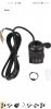
Have 6 wires on controller red black yellow white brown green for where the throttle goes broke the throttle that came with kit so ordered one of eBay with same coloured 6 wires. Wired it all up but just battery indicator lights up when I press switch but wheel does not spin. Surely wires should be correct if they all same colour if not any idea where they go. Also my peddle assist sensor I have taken it off the bike does that have anything to do with it does that have to be connected in order for throttle to work? Or is it I've connected wires wrong please help as if not I will have to spend more money on a different controller as my controller with 6 wire throttle is no good an will have to buy one with 3 wires
 

Attachments

vfr400

Esteemed Pedelecer
Jun 12, 2011
9,822
3,985
Basildon
You don't have to have a pedal sensor for the throttle to work.

The colours are:
Green battery voltage got LEDs on the throttle
Red 5v power for throttle
Black 0v ground
White Throttle signal
Yellow and Brown are the switch wires.

With everything switched on, you must check with a meter between red and black that you have 5v. that tells you that the controller is switched on, then you can check between white and black while you twist the throttle. It should go from 1.2v to 3.8v.

Some of those throttles are wired slightly differently on OEM bikes. It deepens how they deal with the ignition wire, i.e. the wire that powers the controller.
 

Boyaffy

Finding my (electric) wheels
Aug 2, 2020
22
0
You don't have to have a pedal sensor for the throttle to work.

The colours are:
Green battery voltage got LEDs on the throttle
Red 5v power for throttle
Black 0v ground
White Throttle signal
Yellow and Brown are the switch wires.

With everything switched on, you must check with a meter between red and black that you have 5v. that tells you that the controller is switched on, then you can check between white and black while you twist the throttle. It should go from 1.2v to 3.8v.

Some of those throttles are wired slightly differently on OEM bikes. It deepens how they deal with the ignition wire, i.e. the wire that powers the controller.
Don't have a meter to check any idea what colours I can try and mix only way to give it a try both controller and throttle have same colour wires so any idea which should be swapped around
 

Boyaffy

Finding my (electric) wheels
Aug 2, 2020
22
0
You don't have to have a pedal sensor for the throttle to work.

The colours are:
Green battery voltage got LEDs on the throttle
Red 5v power for throttle
Black 0v ground
White Throttle signal
Yellow and Brown are the switch wires.

With everything switched on, you must check with a meter between red and black that you have 5v. that tells you that the controller is switched on, then you can check between white and black while you twist the throttle. It should go from 1.2v to 3.8v.

Some of those throttles are wired slightly differently on OEM bikes. It deepens how they deal with the ignition wire, i.e. the wire that powers the controller.
The leds are on and switch does switch it on so must be wired correctly? Or is there a chance of a wire being mixed up
 

vfr400

Esteemed Pedelecer
Jun 12, 2011
9,822
3,985
Basildon
Whatever you do, don't try other combinations. If you get it wrong, you can wipe out everything. You shouldn't be messing about with these things without a meter.

Show both sides of your throttle connector so we can see all the wires and their colours. Also show a picture of the controller with all its connectors spread out so that we can see them.
 

Boyaffy

Finding my (electric) wheels
Aug 2, 2020
22
0
Whatever you do, don't try other combinations. If you get it wrong, you can wipe out everything. You shouldn't be messing about with these things without a meter.

Show both sides of your throttle connector so we can see all the wires and their colours. Also show a picture of the controller with all its connectors spread out so that we can see them.
It's a 6 wire throtton there and pas won't work on its own I have to turn the switch on of the throttle in order to get pas working and not many throttles on ebay with 6 wires already tried with wiring up 3 wire throttles but they don't seem to work. Looked on ebay and can't seem to find a cheap controller from UK based seller if there are they are less power or well over 50 quid already spent to much on this bike please any help would be great really need to get this throttle to work
 

Attachments

Boyaffy

Finding my (electric) wheels
Aug 2, 2020
22
0
Whatever you do, don't try other combinations. If you get it wrong, you can wipe out everything. You shouldn't be messing about with these things without a meter.

Show both sides of your throttle connector so we can see all the wires and their colours. Also show a picture of the controller with all its connectors spread out so that we can see them.
I no the wires look like they not connected properly just hooked them up temporarily to check if throttle works then I can solder once it's working all wires are connected properly just throttle doesn't spin wheel just light up battery gauge
 

vfr400

Esteemed Pedelecer
Jun 12, 2011
9,822
3,985
Basildon
If that green wire touched any of the others, you will have done a lot of damage.

You can't proceed without a meter.

These are the basic tests you should do after connecting everything up and switching on.

1. Measure the voltage at controller's battery connector. Obviously should be battery voltage.
2. Measure the voltage on the 5v rail. You can measure that between any ground (black) and any of the reds going to throttle, PAS or motor halls.
3. Check throttle signal wire. Should give about 1v to 4v when you twist the throttle.
4. Check that the PAS is pulsing. measure the PAS signal wire while turning the pedals slowly. Should pulse 5v on and off every time a magnet passes the sensor.
5. Check the motor hall signal wires (blue green and yellow). They should each pulse with 5v going on and off as you rotate the wheel BACKWARDS.
 

Thatsadz

Finding my (electric) wheels
Apr 29, 2020
21
0
If that green wire touched any of the others, you will have done a lot of damage.

You can't proceed without a meter.

These are the basic tests you should do after connecting everything up and switching on.

1. Measure the voltage at controller's battery connector. Obviously should be battery voltage.
2. Measure the voltage on the 5v rail. You can measure that between any ground (black) and any of the reds going to throttle, PAS or motor halls.
3. Check throttle signal wire. Should give about 1v to 4v when you twist the throttle.
4. Check that the PAS is pulsing. measure the PAS signal wire while turning the pedals slowly. Should pulse 5v on and off every time a magnet passes the sensor.
5. Check the motor hall signal wires (blue green and yellow). They should each pulse with 5v going on and off as you rotate the wheel BACKWARDS.
Hi I know this thread was a long time ago but I think my green wire did touch the other wires and now it turns on but doesn’t spin at all. I was replacing my throttle and tried the old one which now doesn’t work.
Do I need a whole new controller?
Thanks please reply ASAP
 

Thatsadz

Finding my (electric) wheels
Apr 29, 2020
21
0
If you don't cooperate, I can't help. The results of the tests should be three numbers and four yes/nos
1. 52v
2. 0v
3. 0v
4. No pas
5. Not sure how to check that
I may be doing something wrong testing I’m no expert
 

vfr400

Esteemed Pedelecer
Jun 12, 2011
9,822
3,985
Basildon
With 0v on the 5v rail, your controller isn't switched on, i.e. no power is coming to it. The 5v part is dumb. As long as the battery gives voltage on the power wire (ignition wire), you get the 5v unless your 5v regulator is blown, but that's not very common. Therefore, your problem is that you have no voltage on the ignition wire. You need to find that wire then find out why it has no voltage, which should be easy.

If you don't know which is your ignition wire, you should show a picture of every connector on your controller, clearly showing the colour of the wires on each one - no birds nest or connectors hanging in front of each other.

To help you understand: Although the battery is connected to the controller by the thick red and black wires, the controller nearly always gets it's power from elsewhere by using a branch from the red wire inside the controller sending it outside on a thin power wire, which would then be connected to the ignition wire either directly or indirectly via a switch of some sort to bring the power back into the controller via the ignition wire. They do that so that you have the possibility to switch the controller on and off while the battery is on. The thick red wire goes directly to the motor to power it, but is blocked by the controller. Basically, the controller is like a gate between the battery and the motor. Under the control of the cpu when powered, it opens the gate the right amount. Without power, the gate remains shut.
 

Thatsadz

Finding my (electric) wheels
Apr 29, 2020
21
0
With 0v on the 5v rail, your controller isn't switched on, i.e. no power is coming to it. The 5v part is dumb. As long as the battery gives voltage on the power wire (ignition wire), you get the 5v unless your 5v regulator is blown, but that's not very common. Therefore, your problem is that you have no voltage on the ignition wire. You need to find that wire then find out why it has no voltage, which should be easy.

If you don't know which is your ignition wire, you should show a picture of every connector on your controller, clearly showing the colour of the wires on each one - no birds nest or connectors hanging in front of each other.

To help you understand: Although the battery is connected to the controller by the thick red and black wires, the controller nearly always gets it's power from elsewhere by using a branch from the red wire inside the controller sending it outside on a thin power wire, which would then be connected to the ignition wire either directly or indirectly via a switch of some sort to bring the power back into the controller via the ignition wire. They do that so that you have the possibility to switch the controller on and off while the battery is on. The thick red wire goes directly to the motor to power it, but is blocked by the controller. Basically, the controller is like a gate between the battery and the motor. Under the control of the cpu when powered, it opens the gate the right amount. Without power, the gate remains shut.
Ok I get you so most likely there is 5v but I just haven’t measured it properly. I’ll have a look at it later on but the battery is definately supplying voltage to the controller