Help! Voilamart 26” front hub looking for repair

WheezyRider

Esteemed Pedelecer
Apr 20, 2020
1,636
907
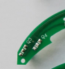
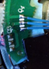
A Well meaning But absolute incompetent frankly got his hands on it . Told me he could help and apart from the terrible soldering he totally guessed what to do and replaced sensors without even checking them . I’m told he replaced them with wrong type 49e . Then he replaced a faulty what I think was a resistor at R2. But he put a capacitor there . I think the board will be replaced . Seen on Ali express . I want to eliminate wiring faults if any first

Oh dear... :rolleyes:

Looking at things briefly, it doesn't look like R2 does anything if no speed limiting wire is connected, (it doesn't look like there is a through board connection at the pad). If that's the case it shouldn't make a difference if it has been swapped with a capacitor.

I'll have another look at mine tomorrow.

Do you have a link to the Ali express board?
 

mikeconnect

Esteemed Pedelecer
Jul 3, 2020
344
9
Warrington , Cheshire
It's interesting that Mike's motor seems to have nothing connected to Q4.

I'm also wondering what that the yellow wire is like under this bit of shrinkwrap:

View attachment 37378

If you look at my motor, the pad marked H (connected to R1/R2) goes to the white wire, which is the speed limiter wire
You know guys whatever the differences in my board to others it worked great before wheel dropped out. Continuity first then I’ve got to decide if board has SM components replaced or buy new board on Ali . BUT NOW I SEE THAT Ali BOARD HAS no R1 And R2. Ok stick with it cable continuity test Sunday .
 

mikeconnect

Esteemed Pedelecer
Jul 3, 2020
344
9
Warrington , Cheshire
With the first controller I had from Voilamart, the white wire was not even soldered onto the PCB inside it! It ran ok though. The Hall sensing part of that controller died after a while, and although noisy, the motor still ran, even with the Hall sensors not connected.

Is your motor running at all?
Motor is dead ever since wheel dropped out
 

mikeconnect

Esteemed Pedelecer
Jul 3, 2020
344
9
Warrington , Cheshire
Oh dear... :rolleyes:

Looking at things briefly, it doesn't look like R2 does anything if no speed limiting wire is connected, (it doesn't look like there is a through board connection at the pad). If that's the case it shouldn't make a difference if it has been swapped with a capacitor.

I'll have another look at mine tomorrow.

Do you have a link to the Ali express board?
I’ll send it but note as in other replies the Ali board has no R1 or R2
 

mikeconnect

Esteemed Pedelecer
Jul 3, 2020
344
9
Warrington , Cheshire
With the first controller I had from Voilamart, the white wire was not even soldered onto the PCB inside it! It ran ok though. The Hall sensing part of that controller died after a while, and although noisy, the motor still ran, even with the Hall sensors not connected.

Is your motor running at all?
Motor not running and certainly not now after disastro man messed with the board
 

mikeconnect

Esteemed Pedelecer
Jul 3, 2020
344
9
Warrington , Cheshire
Last edited:

WheezyRider

Esteemed Pedelecer
Apr 20, 2020
1,636
907
Motor is dead ever since wheel dropped out

Sounds to me like the issue is the main power wires. Either broken internally, or shorted with each other, which could have implications for the controller. As I said, the motor will run, but noisily with the Hall sensor connector completely disconnected.

The power wires on the Voilamart motors are very thin.
 

WheezyRider

Esteemed Pedelecer
Apr 20, 2020
1,636
907

SECOND FROM THE LEFT. But NO R1 or R2
Lithium E bike B on the other photos

Looking at it, the board they are selling is a version 3.0, not the version 4.0, which seems to be used on the Voilamart motors. The connection layout seems to be quite different, so I wouldn't buy it unless someone can confirm for sure that it can be made suitable for use in your motor. The shape of the PCB is slightly different too, so it may not line up properly when installed.
 

WheezyRider

Esteemed Pedelecer
Apr 20, 2020
1,636
907
So what do you think ref no r1/2 would it still work

It depends on the controller somewhat, it may be set up so that if it doesn't get a Hall signal, it shuts down...but I doubt it. I would expect to see something happen, even if the Hall sensors are not functioning, or even disconnected.

I would like to see that you have continuity on the power wires all the way from the controller

37380

37381

See the difference in the end shapes of the PCBs? AliExpress top (v3.0) Ours bottom (v4.0).
 

Nealh

Esteemed Pedelecer
Aug 7, 2014
19,990
8,172
60
West Sx RH
Continuity test first Mike, just to confirm a continuity wire test is the two far extremes of the wire ends. In your case as you have no motor wire connection about 10/12" away, you will have to probe the same coloured wire at the controller via it's connector. One needs to know that all 8 wires when tested go BEEP.
The fact the motor spun out it is probable that one or more wires within the black sheath may be broken or shorted to another.
Once you have done the tests, depending on the results you may then have to test the controller mosfets to see if they are ok as well. A duff mosfet means no motor power.
 
Last edited:

mikeconnect

Esteemed Pedelecer
Jul 3, 2020
344
9
Warrington , Cheshire
Looking at it, the board they are selling is a version 3.0, not the version 4.0, which seems to be used on the Voilamart motors. The connection layout seems to be quite different, so I wouldn't buy it unless someone can confirm for sure that it can be made suitable for use in your motor. The shape of the PCB is slightly different too, so it may not line up properly when installed.
I’ll look again . I only saw the R1 and R2 missing That’s why I asked if it would work without them
 

mikeconnect

Esteemed Pedelecer
Jul 3, 2020
344
9
Warrington , Cheshire
Continuity test first Mike, just to confirm a continuity wire test is the two far extremes of the wire ends. In your case as you have no motor wire connection about 10/12" away, you will have to probe the same coloured wire at the controller via it's connector. One needs to know that all 8 wires when tested go BEEP.
The fact the motor spun out it is probable that one or more wires within the black sheath may be broken or shorted to another.
Once you have done the tests, depending on the results you may then have to test the controller mosfets to see if they are ok as well. A duff mosfet means no motor power.
I think once I’ve checked continuity to eliminate wiring and if wiring is ok , I’ll need to get someone to sort the PCB out . It’s all bit too much for me . By the way I just bought another Giant suede At good price. Only just picked it up so not fully checked but it runs . Sold as faulty but only fault (so far ) is battery doesn’t fully charge . I’ve got a reasonable battery on mine so happy days . I’ll use it on this one . I’m back on the road again . I Couldn’t wait to sort this one out and this was good price . Seen em going for almost double
 

mikeconnect

Esteemed Pedelecer
Jul 3, 2020
344
9
Warrington , Cheshire
Just for my own understanding, I'd like to know what those two components do, marked R1 and R2. Is there any chance that you could scrape the via hole on the corner of the "H" and test continuity to every single solder pad to see where it goes?
Only just saw this . Will check tomorrow cos it’s relevant to that Ali board you showed me with no R1 or R2
 

WheezyRider

Esteemed Pedelecer
Apr 20, 2020
1,636
907
Only just saw this . Will check tomorrow cos it’s relevant to that Ali board you showed me with no R1 or R2
I put a multimeter on the resistors and got 400k for R1 and 350k for R2, although that was in circuit, so values will be affected by what else is connected.
 

WheezyRider

Esteemed Pedelecer
Apr 20, 2020
1,636
907
I think once I’ve checked continuity to eliminate wiring and if wiring is ok , I’ll need to get someone to sort the PCB out . It’s all bit too much for me . By the way I just bought another Giant suede At good price. Only just picked it up so not fully checked but it runs . Sold as faulty but only fault (so far ) is battery doesn’t fully charge . I’ve got a reasonable battery on mine so happy days . I’ll use it on this one . I’m back on the road again . I Couldn’t wait to sort this one out and this was good price . Seen em going for almost double
I always say, one e-bike is not enough, you've got to have two so that you can be working on one while using the other :)
 
  • Like
Reactions: mikeconnect

sjpt

Esteemed Pedelecer
Jun 8, 2018
3,642
2,652
Winchester
I always say, one e-bike is not enough, you've got to have two so that you can be working on one while using the other :)
That sounds even hairier than texting on a phone while using your bike.
 
  • :D
Reactions: WheezyRider

vfr400

Esteemed Pedelecer
Jun 12, 2011
9,822
3,985
Basildon
I put a multimeter on the resistors and got 400k for R1 and 350k for R2, although that was in circuit, so values will be affected by what else is connected.
They're capacitors, not resistors. What I need Know is where the via hole goes, so probe from the bottom of one or the top of the other to see what other pad/s it's connected to.