Help! Voilamart 26” front hub looking for repair

WheezyRider

Esteemed Pedelecer
Apr 20, 2020
1,632
907
They're capacitors, not resistors. What I need Know is where the via hole goes, so probe from the bottom of one or the top of the other to see what other pad/s it's connected to.
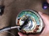
As you say, they look like capacitors, not like normal surface mount resistors and I suppose the "R" label has thrown us off the scent :)

I'll try and do a bit of tracing tomorrow.
 

mikeconnect

Esteemed Pedelecer
Jul 3, 2020
344
9
Warrington , Cheshire
Only just saw this . Will check tomorrow cos it’s relevant to that Ali board you showed me with no R1 or R2
By the way R1 which had not been replaced shows 328 ohm . I assume I’m doing it correctly . The 200 ohm setting stayed on 1 and the 2000 showed 328. Does this mean that R2 needs a resistor of same value ??
 

mikeconnect

Esteemed Pedelecer
Jul 3, 2020
344
9
Warrington , Cheshire
They're capacitors, not resistors. What I need Know is where the via hole goes, so probe from the bottom of one or the top of the other to see what other pad/s it's connected to.
Am I mistaken or are these circuits circled in yellow broken ? after the crazy guy did his terrible soldering on sensors I’m thinking this PCB is a write off after that guy got his hands in it . I’ll take advice on that and persist if you think it’s worth it37411
 

mikeconnect

Esteemed Pedelecer
Jul 3, 2020
344
9
Warrington , Cheshire
It depends on the controller somewhat, it may be set up so that if it doesn't get a Hall signal, it shuts down...but I doubt it. I would expect to see something happen, even if the Hall sensors are not functioning, or even disconnected.

I would like to see that you have continuity on the power wires all the way from the controller

View attachment 37380

View attachment 37381

See the difference in the end shapes of the PCBs? AliExpress top (v3.0) Ours bottom (v4.0).
Look at my photo it’s not like yours it’s like the Ali one only no R1 R2
 

vfr400

Esteemed Pedelecer
Jun 12, 2011
9,822
3,985
Basildon
I can’t get a beep on any pad from H hole . Don’t know how much I’m supposed to scrape it but looks like metal around he hole anyway why do I need scrape?
The hole is connected to the bottom of R1 and the top of R2, so you can use one of those two positions for your black probe, then stick your red probe on every single solder joint to see which ones beep. Start with the black wire which is the most likely. If that beeps, then so should the middle leg of each of the four hall sensor positions. If the black wire doesn't beep, find out what positions do.

All this is completely futile while you haven't tested the motor cable.
 

mikeconnect

Esteemed Pedelecer
Jul 3, 2020
344
9
Warrington , Cheshire
The hole is connected to the bottom of R1 and the top of R2, so you can use one of those two positions for your black probe, then stick your red probe on every single solder joint to see which ones beep. Start with the black wire which is the most likely. If that beeps, then so should the middle leg of each of the four hall sensor positions. If the black wire doesn't beep, find out what positions do.

All this is completely futile while you haven't tested the motor cable.
1. It’s not futile because it gives clues ready for after I test the cabling .
2. frankly I doubt I’ll be touching this PCB I’ll be looking for someone to look at it so the more I can tell them the better.
3 dont forget You’re the one that asked this question. And the answer is I put the probe to R2 and it beeps on GND black wire But how do you know R2 is connected to H
4. This may be futile irrespective of wiring test because I think the circuits are damaged near the sensors where this crazy guy did terrible solders. I posted a photo but you’ve not commented on it. Look at the yellow circles 37418
 

vfr400

Esteemed Pedelecer
Jun 12, 2011
9,822
3,985
Basildon
1. It’s not futile because it gives clues ready for after I test the cabling .
2. frankly I doubt I’ll be touching this PCB I’ll be looking for someone to look at it so the more I can tell them the better.
3 dont forget You’re the one that asked this question. And the answer is I put the probe to R2 and it beeps on GND black wire But how do you know R2 is connected to H
4. This may be futile irrespective of wiring test because I think the circuits are damaged near the sensors where this crazy guy did terrible solders. I posted a photo but you’ve not commented on it
When you have a problem with an ebike, you have to test it in a logical sequence so that you can answer two questions: what's causing the issue and what do I have to do to fix it? Obviously, what you have to do to fix it depends on what's wrong with it.

In your case, every person thats come on here agrees that the most likely fault with your motor is that the cable is damaged. If it is, your motor is scrap, so no point in worrying about anything else other than where to get a replacement motor. All these pages of writing are a complete waste of time other than building our knowledge base to somebody that might have different issues.

Please don't waste more time. Test the bloody cable!
 

mikeconnect

Esteemed Pedelecer
Jul 3, 2020
344
9
Warrington , Cheshire
When you have a problem with an ebike, you have to test it in a logical sequence so that you can answer two questions: what's causing the issue and what do I have to do to fix it? Obviously, what you have to do to fix it depends on what's wrong with it.

In your case, every person thats come on here agrees that the most likely fault with your motor is that the cable is damaged. If it is, your motor is scrap, so no point in worrying about anything else other than where to get a replacement motor. All these pages of writing are a complete waste of time other than building our knowledge base to somebody that might have different issues.

Please don't waste more time. Test the bloody cable!
You may be right but in that case why did you ask the question about the Bloody H hole
 

Nealh

Esteemed Pedelecer
Aug 7, 2014
19,988
8,170
60
West Sx RH
As vfr has mentioned a logical sequence of testing components is required before trying to jump two steps ahead, the jumping ahead steps prove little until the first steps are carried out.
In the case of a motor spinning out of the D/O's first step is to confirm all motor wires show continuation irrelevant of whether damage can be seen or not. Should this provide a negative result then damage is likely elsewhere so the motor pcb is one possibility, before deciding if the motor pcb is at fault one needs to also check the controller Mosfets as well as a negative result here will also mean no power to the hub irrelevant of any work you do.
 

mikeconnect

Esteemed Pedelecer
Jul 3, 2020
344
9
Warrington , Cheshire
As vfr has mentioned a logical sequence of testing components is required before trying to jump two steps ahead, the jumping ahead steps prove little until the first steps are carried out.
In the case of a motor spinning out of the D/O's first step is to confirm all motor wires show continuation irrelevant of whether damage can be seen or not. Should this provide a negative result then damage is likely elsewhere so the motor pcb is one possibility, before deciding if the motor pcb is at fault one needs to also check the controller Mosfets as well as a negative result here will also mean no power to the hub irrelevant of any work you do.
Agreed .
But VFR asked me the question about what the h hole is connected to so I answered him . I’ve been busy working but I’ve got the motor out so I answered his question before I got this fiddly cowling off. Now I’m trying to get cowling off. I’ll check the bloody wiring today And won’t ask a questionAbout anything else till I’ve done it . Haha.
 

vfr400

Esteemed Pedelecer
Jun 12, 2011
9,822
3,985
Basildon
Agreed .
But VFR asked me the question about what the h hole is connected to so I answered him . I’ve been busy working but I’ve got the motor out so I answered his question before I got this fiddly cowling off. Now I’m trying to get cowling off. I’ll check the bloody wiring today And won’t ask a questionAbout anything else till I’ve done it . Haha.
I asked that question to Wheezyrider for my own knowledge. Later, you started to test that on his behalf, so I encouraged you to complete the test.
 

Nealh

Esteemed Pedelecer
Aug 7, 2014
19,988
8,170
60
West Sx RH
In the first reply #2 I asked you to check the wire continuity over 50 posts a go and we still are no further forward of knowing.
We start with the known basics to try and disregard them.

To tell a lie we haven't asked about the battery, at the time it worked so assume it is giving out good voltage still ? Though I am digressing from the main electronic testing issues.
 

mikeconnect

Esteemed Pedelecer
Jul 3, 2020
344
9
Warrington , Cheshire
I asked that question to Wheezyrider for my own knowledge. Later, you started to test that on his behalf, so I encouraged you to complete the test.
Haha ok .
Right every body I’m gonna do the cable test but I need help . Have you ever removed the cowling from giant suede . All screws removed it’s loose but looks like I may have to remove pedal crank and pedal sensor to fully remove cowling . Photo attached pls advise . Then we’ll
I asked that question to Wheezyrider for my own knowledge. Later, you started to test that on his behalf, so I encouraged you to complete the test.
hah ok . Wire test only before any other questions .BUT have you ever taken cowling off a Giant Suede? I’ve removed all screws and it’s loose but maybe you need to remove pedal and pedal sensor to fully remove ??? Photo attached
Don’t know if I can access from chain side
 

Attachments

Last edited:

mikeconnect

Esteemed Pedelecer
Jul 3, 2020
344
9
Warrington , Cheshire
In the first reply #2 I asked you to check the wire continuity over 50 posts a go and we still are no further forward of knowing.
We start with the known basics to try and disregard them.

To tell a lie we haven't asked about the battery, at the time it worked so assume it is giving out good voltage still ? Though I am digressing from the main electronic testing issues.
Battery’s ok and look at cowling photo to help me remove to test wires
 

mikeconnect

Esteemed Pedelecer
Jul 3, 2020
344
9
Warrington , Cheshire
Ok IM GETTING CONTINUITY FROM ALL 5 wires on PCB . What next?
There’s the 3 thicker wires Green yellow and blue in the motor end that run through the same cable . I’ve found their contacts at controller end I’ll try to make a contact at motor end and test but I think they’re unlikely cos they’re thicker sturdier and if the thin PCB wires survived in sure they will have too
 
Last edited:

mikeconnect

Esteemed Pedelecer
Jul 3, 2020
344
9
Warrington , Cheshire
Ok IM GETTING CONTINUITY FROM ALL 5 wires on PCB . What next?
There’s the 3 thicker wires Green yellow and blue in the motor end that run through the same cable . I’ve found their contacts at controller end I’ll try to make a contact at motor end and test but I think they’re unlikely cos they’re thicker sturdier and if the thin PCB wires survived in sure they will have too
Ok I see its mosfet next. Where are they exactly and how do I test them plz