Wiring issues - Cree XML-T6 light

103Alex1

Esteemed Pedelecer
Sep 29, 2012
2,228
67
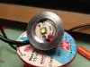
Got a wee issue on my 1000Lm light...

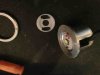
The sheath on the cable which exits the light housing running to the connector has come away from the housing quite considerably. A roadside repair to the quick-release bracket I hadn't screwed in properly in very poor light is likely the culprit :)o).

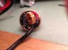
Light cut out and I initially tried to wrap the wires in tape to get it working (I am assuming black and red wires should not touch(?!!) ) .. and it worked for a day before my having to fiddle again. Photo here :

20130116_012412[1].jpg

Am I right in assuming that i need to insulate the copper wires which have become exposed from the protective sheaths and that these should not touch each other (light didn't work when they did) ? Is there anything neat I can do to make more weatherproof and long-term fix than wrapping the black and red wires again and hoping for the best ?

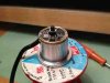
I've taken the lens and casing off to expose the light filament, but the wiring is behind this within a robust unit and not sure whether I should / can pull it out to get at the wiring exiting the light so as to cut and refix after stripping back the main thick outer black cable sheath to expose intact red / black wires (if that makes any sense ... :confused:)
 
Last edited:

NRG

Esteemed Pedelecer
Oct 6, 2009
2,592
10
......

Am I right in assuming that i need to insulate the copper wires which have become exposed from the protective sheaths and that these should not touch each other (light didn't work when they did) ?
Yes!

Is there anything neat I can do to make more weatherproof and long-term fix than wrapping the black and red wires again and hoping for the best ?
If there's enough room IE: the hole is big enough you could push a grommet into the hole and the wire through that, then secure with a tie wrap around the wire inside the case...if there's room.

You'll obviously need to desolder the wires, strip back the cable to find good insulation and reconnect...
 

NRG

Esteemed Pedelecer
Oct 6, 2009
2,592
10
Scratch that :-/

The handle bar mount secures the cable, de-solder the cable, strip it back to good insulation and re-solder. Make sure the handle bar clamp is tight!
 
D

Deleted member 4366

Guest
I can't see which one you've got from the photo, but assuming it's like mine:

Unscrew the front;
unscrew the screw in the clamp;
Push the wire in and at the same time wiggle the whole interior out;
You will then see that the two wires are soldered to pads at the back of the driver unit. They only go one way round so make a note of which way or mark them;
Unsolder the wires;
Trim the ends (You might want to think about a grommet);
Resolder them;
Reassemble.
 

103Alex1

Esteemed Pedelecer
Sep 29, 2012
2,228
67
Thanks for the comments ... been having a go today ... main problem is this bit :

Push the wire in and at the same time wiggle the whole interior out
The wire is very difficult to push through as the exit hole from the housing is very small. The interior also seems to be prevented from wiggling out by a moulding on the inside of the housing so you can't get to the wiring behind.

This is the model : CREE XM-L T6 LED 1000 Lumen Bike Light & Headlamp Kit | C&B SEEN Ltd
 

103Alex1

Esteemed Pedelecer
Sep 29, 2012
2,228
67
Yes - the clamp is off so the base of the unit is as per the pic earlier in the thread. The front of the light screws off in order to reveal the lens and cone inside. I took the lens and cone out and there is a small moulding which secures the rear of the light, filament, etc in the back of the unit. Can't see how to get that out past the moulding without breaking it.

The back of the unit (behind the screw-off front) is a heavy-duty moulded unit - not sure you can get into it any other way.
 

NRG

Esteemed Pedelecer
Oct 6, 2009
2,592
10
It's screwed in, you can see the ring in this photo ImageUploadedByTapatalk1358345765.132576.jpg

Use small snipe nose pliers to turn the ring using those two small indents.

Looking at it I think you'll need to desolder the wires from the top of the LED and prise out the bottom PCB and brass ring to get access to the main wire.

ImageUploadedByTapatalk1358345983.548438.jpg

ImageUploadedByTapatalk1358345995.298844.jpg


---------------------------------
Posted using Tapatalk :)
 

NRG

Esteemed Pedelecer
Oct 6, 2009
2,592
10
Just shows how fragile the wires are....broke mine putting it back together!
 

103Alex1

Esteemed Pedelecer
Sep 29, 2012
2,228
67
Thanks !!! We're on a roll ...

I've unscrewed it (had just become seized having been out in the cold but wiggled it loose). Have pulled back the PCB and I can see the soldering points.

20130116_143853[1].jpg

So next step .... I've never soldered before. Will likely have some to do if I go ahead with the bike conversion so this seems a pretty good place to start having a go and getting to practice how.

What sort of soldering iron do I need to go and get, and and recommendations on what soldering compound to buy ? I may soon need a bit more hand-holding :)o) but usually OK once I've done stuff a couple of times.

Also for stripping back the main cable (black sheath) without damaging the red / black thin wires instead, what do people normally use ? My instinct is careful use of a stanley knife but if any better ways, suggestions welcome.

:)

Just shows how fragile the wires are....broke mine putting it back together!
Just seen this ... :( ... fwiw I am genuinely grateful for the pics and guidance !!!
 
Last edited:

NRG

Esteemed Pedelecer
Oct 6, 2009
2,592
10
That's one fiddley job. Yours is different to mine! The brass ring is a friction fit, desolder the LED wires and use a screw driver to part the brass ring from the alloy housing.

Resolder the broken wire and then have fun getting the brass ring back in place. I had to use a small tack hammer to persuade it to go back (mind the components!) or you could use a modlers vice...

ImageUploadedByTapatalk1358348619.758969.jpg

ImageUploadedByTapatalk1358348703.493006.jpg

ImageUploadedByTapatalk1358348719.226271.jpg

ImageUploadedByTapatalk1358348735.125573.jpg


---------------------------------
Posted using Tapatalk :)
 
Last edited:

NRG

Esteemed Pedelecer
Oct 6, 2009
2,592
10

103Alex1

Esteemed Pedelecer
Sep 29, 2012
2,228
67
You could use a stanley knife just be careful not to 'nick' the inner wires. For a soldering iron and as you've not done it before I'd use a miniature 15w iron like this one:

15W Miniature Soldering Iron Type C : Mains Soldering Irons : Maplin Electronics

That way the bit will be small enough and you'll put less heat in to the surrounding components, practice first on some spare wire...
Thanks - I've ordered one to collect in-store. Do I need to buy solder also and will this be good enough to work with controllers etc too ?
 

Old_Dave

Esteemed Pedelecer
Sep 15, 2012
1,211
2
Dumfries & Galloway
Talking of solder.....

The world seems to be going to 'lead free' .. I say continue to use 60/40 cos that lead free stuff has a higher melting point and also wears out soldering iron tips ( even the special expensive tips sold as being suitable for lead free)

Oh and +1 with the solder station that d8veh suggested.


Sent from my iPhone using Tapatalk
 
D

Deleted member 4366

Guest
Talking of solder.....

The world seems to be going to 'lead free' .. I say continue to use 60/40 cos that lead free stuff has a higher melting point and also wears out soldering iron tips ( even the special expensive tips sold as being suitable for lead free)

Oh and +1 with the solder station that d8veh suggested.


Sent from my iPhone using Tapatalk
I teach/taught electronics at secondary school. We tried lead free and the results were terrible. We tried a lot of different solders, none of which were anything like as easy as the traditional flux cored 60/40 tin/llead solder, which is getting harder to find, although still plenty on ebay.
 

NRG

Esteemed Pedelecer
Oct 6, 2009
2,592
10
I think that this one is better for ebikes because it has enough power to do battery connections. You can turn the heat up and down for different jobs:
50W Solder Station : Temperature Controlled Irons & Solder Stations : Maplin Electronics
For the solder, you want standard 60/40 tin/lead solder but I can't see it in their listings. You might have to get it from ebay or any DIY shop.
Hmmmm not convinced, I had one and its built to a price. It also packed up after a few weeks of use.

It ships with a spike tip, so you need to also buy the accessory Tip pack to go with it...
 
D

Deleted member 4366

Guest
Hmmmm not convinced, I had one and its built to a price. It also packed up after a few weeks of use.

It ships with a spike tip, so you need to also buy the accessory Tip pack to go with it...
Ive been using it for about 3 months now and seems pretty good. The only thing I don't like is the lack of scale on the temperature control, but I've got the settings more or less figured out now.