James28
Members
-
Joined
-
Last visited
-
All my switch does is disconnect the battery from the controller. LifePo4 ebike full build | Pedelecs - Electric Bike Community There's my build if you were interested. this is sounding more and more like I should series in another 4 cells and see how 48v runs compared to the 36v at slower speeds
-
It is a G020 hub winding code 10 so its a little quicker but it is 36 v so 48v might put the rpm up quite a bit more than a 48v code 12. I'm glad to here overheating is not a problem but would a motor with a lower winding speed have an easier time getting up a hill as apposed to a higher rpm motor. This is essentially what I'm trying to achieve by being able to switch the motors efficient rpm by changing the voltage on the fly.
-
I keep a close eye on my voltage already, I was going to wire it so it would effectively just series all the cells together from 12 to 16 Its a good point, I would end up with 12 cells at lower voltage than the extra 4 I'm adding if I only use the extra 4 part time but I though cells would only balance (back charge) if they were connected in parallel and not series. My battery is 12s1p configuration by the way.
-
I do have a switch with a soft start on my main battery at the moment. It has survived a good few hundred uses even after I stopped using the soft start, although I've never switched it on/off under load. the idea is to use something like a 60v 20a relay so I can switch under load. The point you make about the controller I will certainly need to test, I'm using a 36V LifePo4 so full charge is slightly higher than li-ion. there would be no point in trying this if the controller has a problem with the sudden voltage change. I'd never rely on the LVC anyway 2.5v per cell on LifePO4 is just to low for my liking so I watch the voltage while I'm riding anyway. If 48v wont loose me efficiency at low end then I might as well just run it as 48v. I just don't want to subject my 250w motor to any more undue stress as I'm already putting 650W through it already.
-
I've been running a bafang hub motor on 36v for a while now and it gives me reasonable low speed performance and tops out around 20mph which is ok but I would like a higher top speed. If I upgrade my battery to 48v this will give me a higher top speed but I think I'm right in saying this will effectively move the efficiency range to higher rpm and reduce my low speed performance (heating up and straining the motor). I have considered a mid drive but my commute involves quite a bit of flood water and I'm not great at keeping on top of drivetrain maintenance and i like how reliable my hub motor is. I've been wondering for a while whether it is possible to put a 12v battery on my bike that I can turn on with a switch when I'm up to the top speed for 36v (20mph) to make it 48v and allow the motor to spin faster. Effectively giving the bike a second gear without straining the motor at low speed. I'm pretty sure this would work by using a SPDT relay to add the 12v battery to the 36v battery to supply the controller with 48v. My controller is up to it, its a 25A 36v/48v kt controller with 63v capacitors in it so it will survive the voltage. I will be treating the 36v and 12 v batteries separately so they will have their own BMS and I will charge them separately. I'm just after more electronically experienced people to tell me if this is viable or impossible before I waste time and money in trying it out.
-
My main concern is with the cells themselves. I made a load of dummy cells out of pvc pipe (my cells are 33mm diameter x 140mm), put a wire through the middle, terminals on each end and filled them with sand to get the right weight. I fixed the pack together as if i had the real cells in place and kicked it down the stairs, threw it out of a 2nd storey window and towed it around on the mountain bike for a while to make sure it would be alright.
-
I have wondered how people managed to get away with batteries mounted only on the bottle cage mounts. It seems like a lot to put on 2 bolts to me. I see no designs of ebikes (particuly factory ebikes) make much if any effort to protect the battery from shock. Maybe i just think they are more fragile than what they are. 1500w makes mine look like a childs toy
-
I wanted to hear your views on how necessary you think it is to isolate a battery from the general road vibrations and shock you get from riding. Ie hitting a pothole hole or just a generally uneven surface. Obviously full suspension bikes and fat bikes would have most of this isolated but what about fully rigid bikes? Are the batteries totally fine with the general vibrations and knocks you get from riding around? My battery is mounted to a cross bike which i fitted some shwable big apples to to try and protect my components a bit. When i designed my enclosure i did have this in mind but being limited with space I am limited on what i could do to isolate it. I fitted foam around the battery in the enclosure and used bushings and more foam to fit the enclosure to some aluminium plates i have mounted on the frame. (My lifepo4 build thread has more detail of what i did) Im just looking to make my battery box and small as i can so if its just not necessary to protect it like i have done then i can leave it out of my new design to keep the size down. I thought this would be an interesting discussion, if the general consensus is that its not really known then im happy to go for it and report my findings after a few hundred miles. Bear in mind im using lithium iron phosphate and not lithium ion cells
-
I did consider it but the mechanical stregnth is no-where near as good as leaded or unleaded solder. My design at the time needed a decent mechanical bond between the cells. I know you shouldn't rely on solder for that but its plenty capable on joints of this size. I did try to assemble the pack in such a way that i could remove a cell if needed but this didnt work out too well in reality and it was a real pain to get the bad cell out. After destroying a cell and wrestling the thing out of a fully built pack i decided to redesign it so it was a bit more serviceable. Now its just a few nuts and the pack is disassembled in minutes without pulling it around too much which i felt just stressed all the other terminals on the batteries. I use indium bismuth solder a fair bit at work and it melts at an even lower tempreature (about 70C). Im pretty confident using this wouldn't heat up the cells very much if at all past what the recomended limit is for the cell. My choice to use the foil was purely based on ease of assembly and dissasembly. Copper is only 5 times more conductive than indium and my joints have more than 5 times the surface area recomended for the current im drawing. I retested the resistance of the battery after assembly and saw no difference between a built pack and the individual cells.
-
I suppose it could be but i not had an issue. I did test it by switching it while underload and it seems to have survived
-
Its about £15 for a sheet from aliexpress for 100mmx100mmx0.1mm. I have access to an xray machine at work so i tested it for purity, the xray showed 99% + purity
-
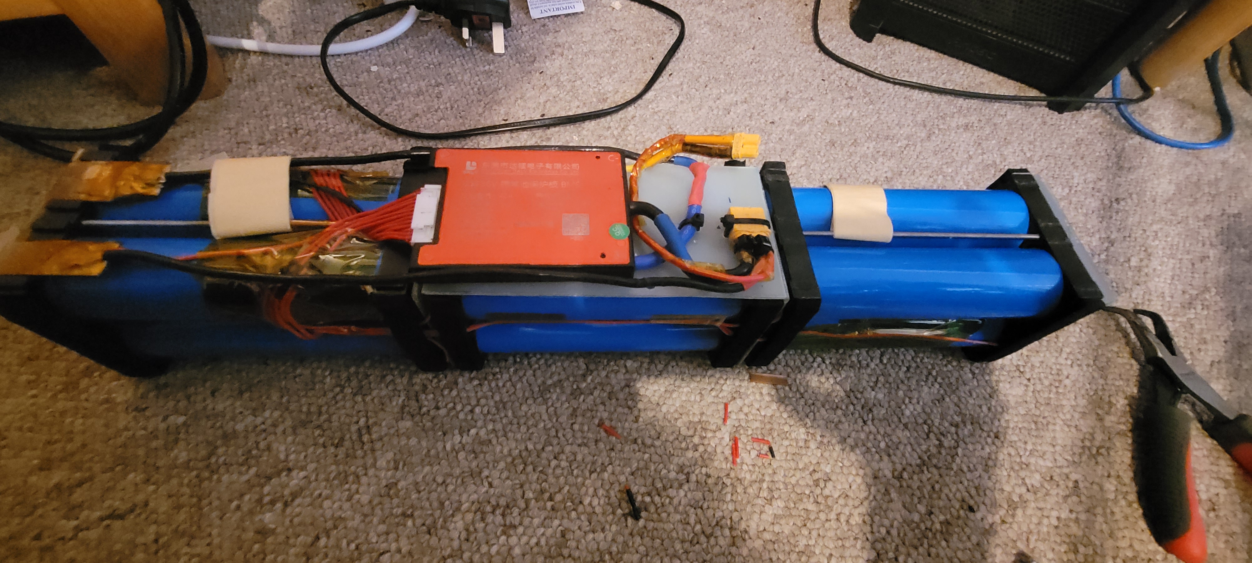
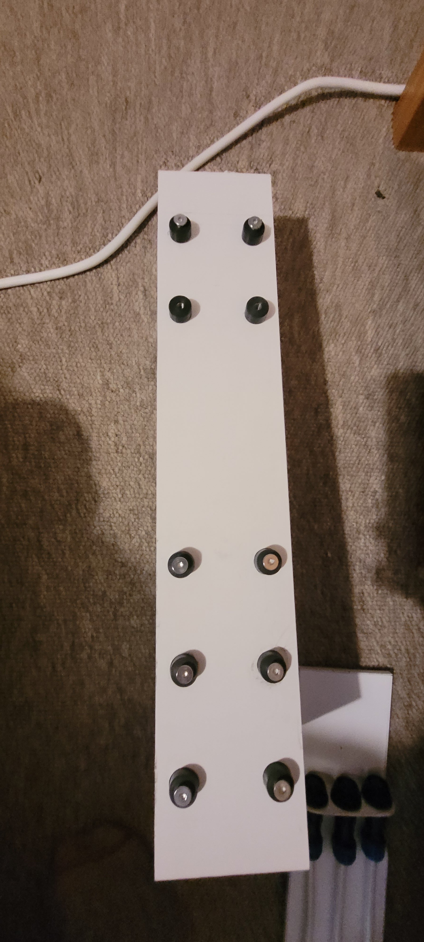
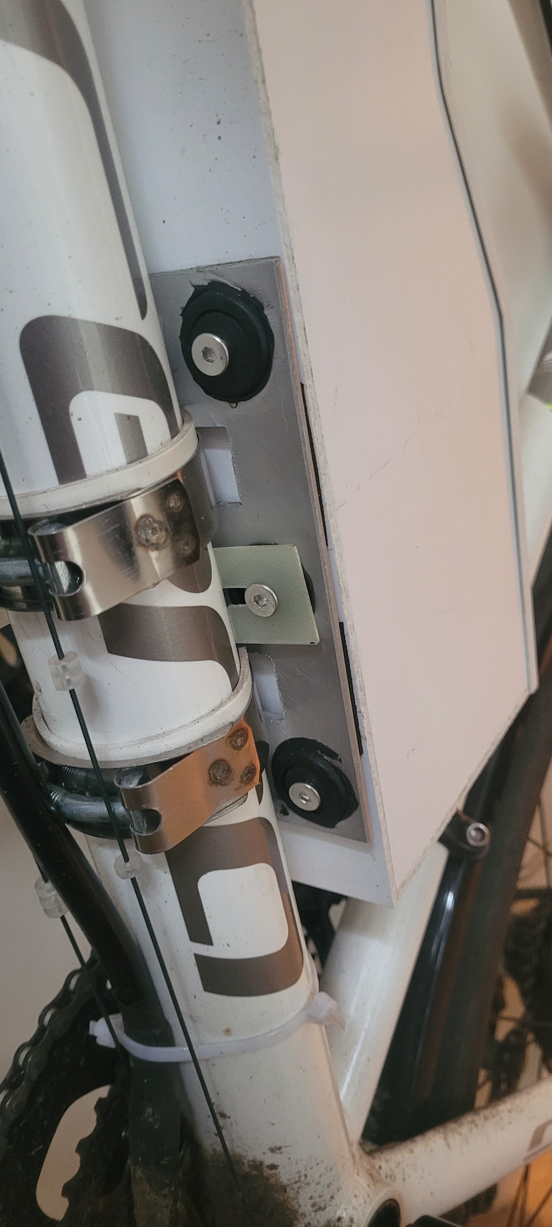
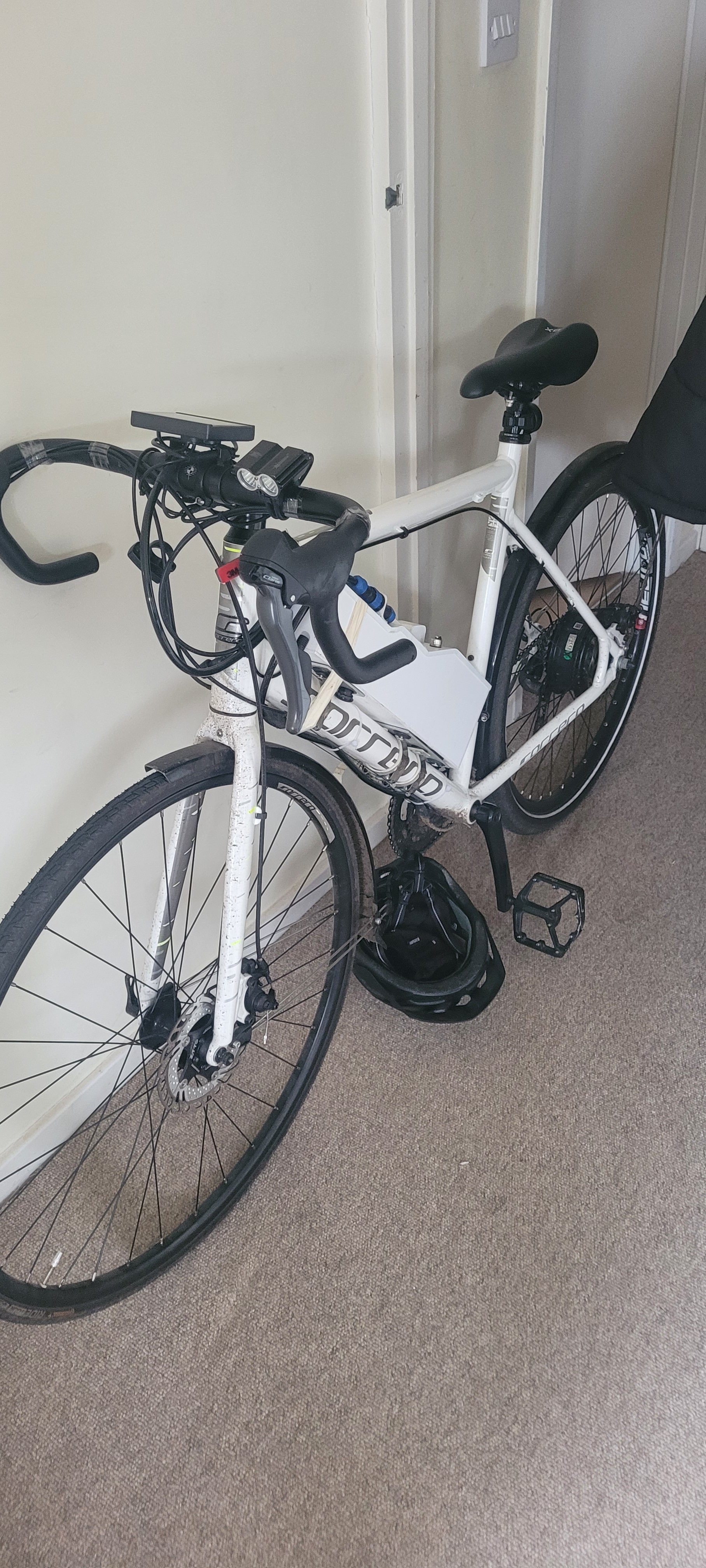
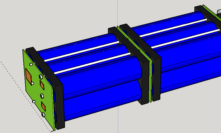
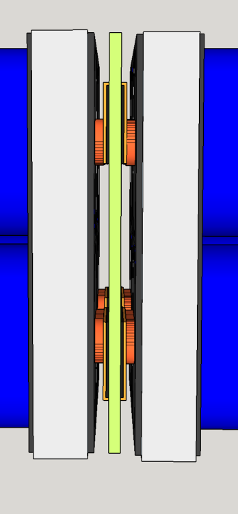
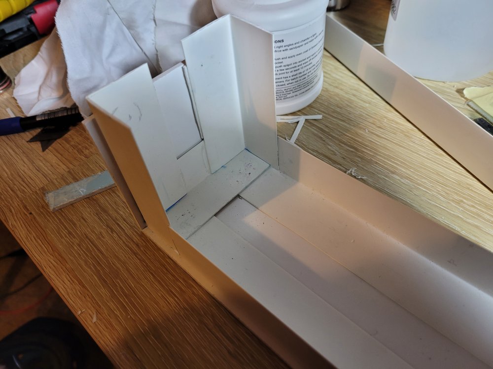
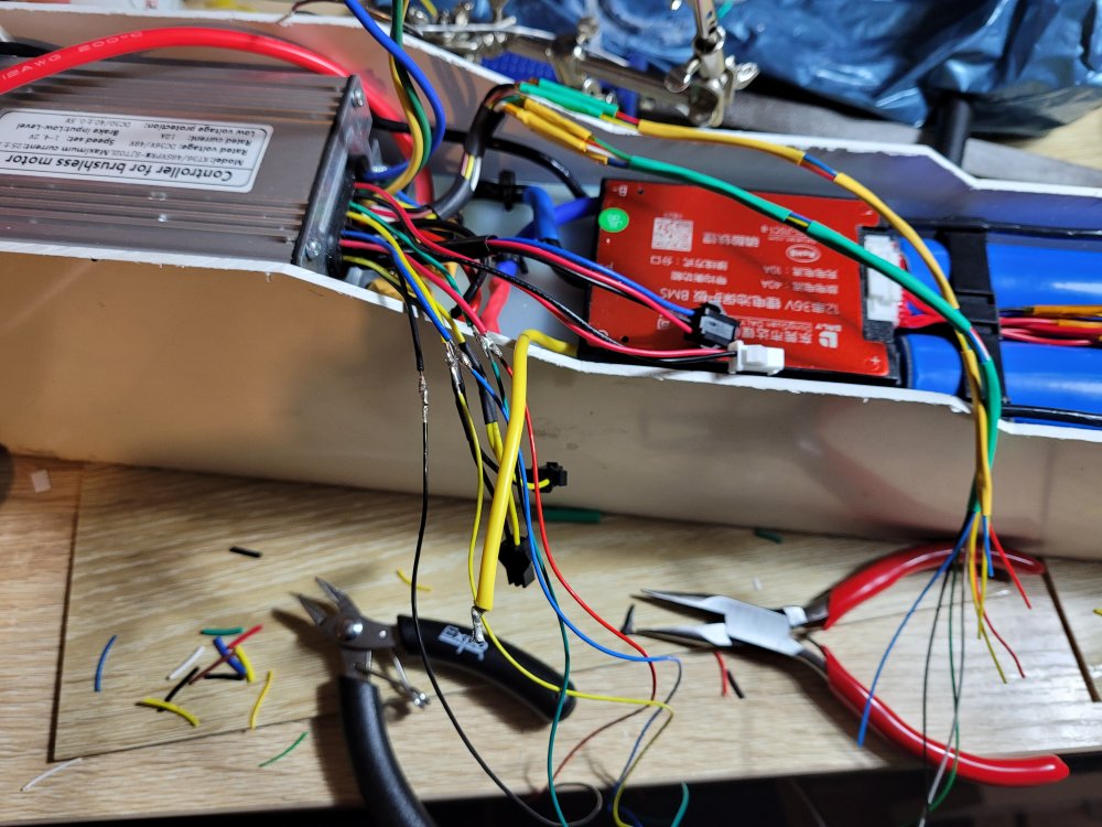
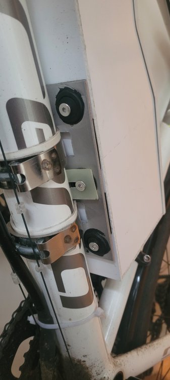
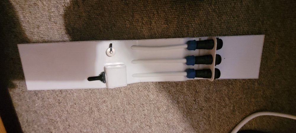
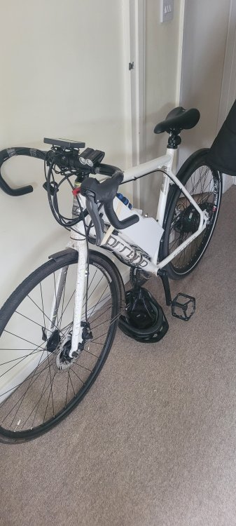
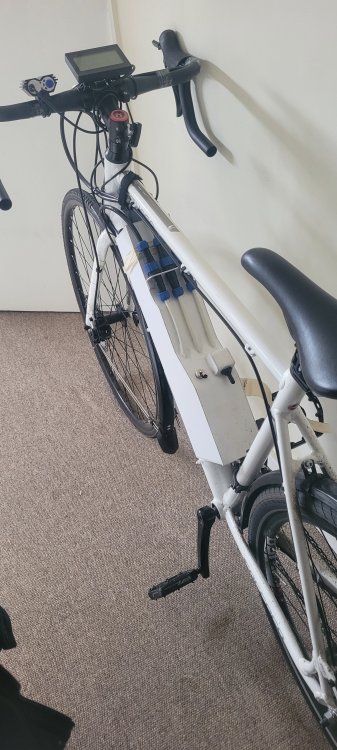
Building an E-bike is something I've wanted to do for a very long time and last year I finally got round to it, hopefully there is some value in here to anybody looking to do the same thing. In this write up I will cover pretty much my whole build and share my experience and hopefully inspires some people enough to build something themselves. The main reason I wanted to build an E-bike rather than buy one is because you cant buy an E-bike with Lifepo4 Cells. Something that really doesn't seem to be common practice amongst builders. Most seem to believe they are old technology and have no place on an E-bike, some even go as far as saying there is no benefit whatsoever but I disagree. I'm hoping this build will show people it is a more viable chemistry for an E-bike than people give it credit for and help anybody build a similar system that values the same advantages lifepo4 possesses over Li-ion cells that I do. Why was I so set on using Lifepo4? The biggest reason for using Lifepo4 was the safety factor, there is enough proof out there that LI-ion cells can spontaneously combust and how hard it is to get lifepo4 to do anything interesting in this regard. Yes I know its rare and the risk can be mitigated through safe charging/discharging practices, storage, BMS, ECT, but it can never be fully eliminated and for me if this ever occurred living in a 2nd floor flat my options are pretty limited in the event of a fire. Lifepo4 is good for 2000 – 3000 cycles vs the 500 of li-ion. To me this is a no brainer on a commuter as it just enhances reliability and cost saving when batteries need replacing. Li-ion doesn't do particularly well in temperatures below 0C so with a bike parked outside on days where the temperature barely reaches -5C in the winter (such as the winter just past) you'll end up pushing that battery pretty hard. Lifepo4 is good for -10C and will suffer far less in winter conditions (I'll share my observations on my on battery later). I know there are obvious advantages on using Li-ion over Lifepo4 but none of these I view as critical unless building something insane such as 1kw+ builds. Higher energy and power density high quality cells are far easier to source far more people have tried and tested builds with Li-ion Lifepo4 is heavier (I really don't see the issue with the small weight penalty when your being propelled by an electric motor) space is much more important IMO. You get better range for the same size with Li-ion but unless you need 30+ miles no pedalling at 25+mph then its not such a huge issue. Hopefully I have made my case clear for the lifepo4 chemistry. The cells Sourcing Li-ion cells and designing them into a usable E-bike battery is quite frankly easy but with lifepo4 its not so much due to their very limited availability in smaller sizes. I spent a very long time searching and weighing up my options considering factors such as cell size and weight (this varies wildly with different cells) energy density cost ease of assembly I eventually settled on a 15AH 33140 cell made by Guoxuan, I found out that a huge number of these cells were ordered by a large American car manufacture (the brand wasn't stated) so I figured if they were good enough for them they were good enough for me. The cells weigh 276g and have an internal resistance of 15 milliohms when I tested them. I load tested each cell with a 15 amp draw and they returned 14.5Ah or 46.4wh. Lifepo4 voltage falls off a cliff when it becomes empty so I stopped my test just as this started to happen (2.8v when under load in my case), I did test beyond this and got 15.5Ah but I didn't feel this would be useful in the real world. This leaves me with an energy density of 168wh/KG and 387wh/L. For the test I used a cheap battery tester from Aliexpress, I supplemented it with a fluke multimeter and an ammeter for more accurate results. Something to bear in mind Lifepo4 cells are only able to comfortably produce about 1.5C of current draw. So in the case for these cells this is a little over 20amps (plenty for a modest ebike build). I Found that most sellers vastly overstate the performance of these cells stating ludicrous discharge rates of 5C and internal resistance of 3 milliohms, these cells are capable of nothing like that but they are plenty good enough for my application. There are plenty of sellers of these cells on Aliexpress and can be found easily by searching 33140 lifepo4 cells. The Battery Build Designing the battery itself was the hard part. The cells are large enough to not need any parallel connections so I built a 12S 1P pack For 36v. For those that don't know Lifepo4 has a nominal voltage of 3.2v a cell so more are needed to reach 36v. Because the cells are so large (33mm x 140mm cylinders), I decided to make a dummy pack out of some PVC pipe the same size as the cells to make sure my design would fit my frame before purchasing any cells. I know usually people hot glue or similar 18650s together and join them by spot welding nickel strips. This is fine when the current load is split between parallel connections and multiple strips can be used to make the series connections but not when each cell is carrying the full load. Nickel strips were out because they cant carry 20 amps without being massive, I couldn't economically spot weld it to the copper contacts of the cells anyway. Copper contacts were the only option but this is even harder to spot weld so that was also out of the question. I tried soldering the cells together with copper strips and a huge soldering iron but I found this just heated up the cells no matter how fast I was and I ended up destroying one. So in the end my solution was to use copper strips between the cells to make the connections and compressing the whole pack with threaded rod. I used indium shim between the cell contact and the copper contact. Indium very effectively cold welds to copper and will creep into all the imperfections in the copper giving a much better contact. I annealed the copper plates to soften them up to aid conformity when compressing. I guess some sort of conductive compound would work too. ( the cross sectional contact area is about 70mm2 which is more than enough) (I used 3 banks of 2x2, 4 cells in each bank this is a design I'm working on for a 16s Pack) I managed to find some brackets designed to hold these cells together and I used some G10 plate in-between the banks of cells to hold the copper contact plates. I hope this is clear as to how I mounted the copper contact plate through a slot cut into the g10. The black strip in-between the g10 and the copper plate is just some rubber for some expansion room. So there we have it, a 36v 550WH pack capable of 20 amps constant discharge which gives me about 700watts available. The whole pack including all the fixtures and contacts weighed in at 3.5KG giving a energy density at the pack level of 157wh/kg and measured 70x70x440mm giving 255wh/L. I used a simple Daly BMS which seems to be working, the pack has stayed in balance over the last 500 miles. I brought a 5 amp lifepo4 charger to charge it which would take 3 hours from completely flat to full, not that I ever drain it that far. I have since tidied up all of my wiring, just one of those smalls things that I didn't plan too well initially, this was my first battery build after all) Motor and controller As this was my first E-bike build I wanted to use something tried and tested. So I went for a 9 mosfet KT sinewave controller rated for 22 amps in conjunction with a kt lcd 3 display. My motor is a rear bafang G020 250w code 10 motor, this runs at 310rpm. Enclosure and mounting I think this was the hardest part of my build considering my requirements. wanted all components housed in a single enclosure clean wiring completely waterproof removable battery I've seen some pretty dodgy looking DIY E-bikes out there and I didn't want to fall in to this camp. I also see a lot of bikes id be scared to take through a small puddle and some that look so illegal they are just asking for it to be confiscated. Enclosure I decided I wasn't going to over engineer this, I felt I should build my first revision just to see how it went. I used some PVC angle to make a frame and covered it in panels made from 3mm PVC sheet. Its really easy stuff to work with, waterproof and it glues together very well using plumbers cement (basically jellied acetone). I fitted some neoprene foam to the battery pack in an attempt to give it some shock protection, i'm not entirely sure it was as successful as I was hoping but I think it does something. Mounting Actually mounting this 5kg box to a bike is pretty tricky, its far too much to hang off of bottle cage mounts so I fitted 10 small 15x15mm spacers made from PVC with an m5 heli coil through the middle to the bottom of the box which sit in holes I drilled into some aluminium plates which are held onto the frame with exhaust clamps (I used the bottle cage holes just to align the larger plate to keep it central). The pictures hopefully explain this better. I used some plastic tube and some waterproof aviation connectors to get the wires from inside the box to the outside while keeping it all water tight. The connectors allow me to disconnect the battery box from the frame. I made the wiring loom in a similar way, I basically have 1 tube running down the frame to the motor and 1 up to the bars. I tested the waterproofing by dumping everything in the bath. Switch I wanted to have a main switch to prevent the capacitors in the controller from being charged constantly, so I found a 24v switch rated for 25A DC (I know its not ideal but its very hard to find something of a reasonable size, its not switching full current so I figured it would suffice). Its a double throw switch. I fitted a 0.15ohm 5w resistor to one side and the main current lead to the other. The switch with resistor will charge the capacitors in the controller slowly before I switch to main battery power. This will prevent a large spike of current through the switch which could weld the switch contacts together. Finally So none of this actually matters until you put it all together and take it out on the road. In total I added about 8kg to the bike considering what I get out of it I was very happy. Weight was a considerable factor in this build because I have to lug this thing down 3 flights of stairs to get it outside which is why I fitted all this to a road bike frame. The whole bike weighs around 18kg. My commute is 8 miles a day and I use it for 3 days until charging. I give the bike basically no help at all and it can carry me along at 23mph (obviously I run at 15mph for legal reasons). When I did my range test I got 30 miles like this. I have no throttle and only use the pedal sensor to engage the motor so I just spin the cranks and it moves. I have the current set on the controller to about 11 amps giving me about 420watts and get a voltage drop on the battery of about 1.2 volts this is more in the winter after the battery has been out in the freezing cold all day where I see a drop of 1.7 volts. I'm not going to stop with it here, I plan on rebuilding my enclosure from carbon fibre to make it smaller and lighter and building a 16s battery to get 48v with a better smart BMS and a voltage converter so I can run lights off the main battery. Well done if you made it this far, I hope my experiences with this have been interesting and given some ideas to people. I have tried to design this so its can be built with minimal tooling and a bit of skill, I built this in my bedroom without anything more than some very basic tools. I'm more than happy for any questions, criticisms or improvements. More discussion can only be a good thing. Thank you for reading.


-
Im using a kt controller and a kt lcd 3, i believe it calculates speed from inputing the number of poles ( of the motor) x the gear reduction and the wheel size. Its basically all built in.
-
I did wonder at what point spokes became too big for rim drillings. 12/13 seems pretty massive for a bicycle (imo). Pro's can put far more through a wheel than the 400watts im putting though mine with fewer and thinner spokes. The sapim strongs are 13 gauge at the j bend and 14 thoughout the length of the spoke which is ideal for filling the holes in the hub flanges properly.
-
I halved the flange to flange, added 5.6 to the left to give 26.85, took 5.6 off the right side to get 15.65. Which did seem like quite a big difference to me. It looks like i have my left and right mixed up, the calculator im using uses different left and right for the front and back wheels. I used the calculator for the front and figured it wouldn't make any difference for measurments