Motor ID

DeanosBeano

Pedelecer
Aug 22, 2019
36
7
Hi All
I am trying to replace my motor as it's gone kaput and we'll it was a bit underpowered ,can anybody tell me
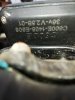
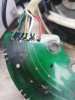
A, the manufacturer of the existing
Model DGW07
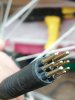
B , does the pin shown look like a standard 9 pin that would fit any equivalent for example bafang motor

Cheers in advance
 

Attachments

DeanosBeano

Pedelecer
Aug 22, 2019
36
7
I think its very close , drop out is a bit short mines 175 mil but hey thats definitely the manufacturer

Thanks for that :)

it lead me here and i think this is the upgrade i need

 
Last edited:

vfr400

Esteemed Pedelecer
Jun 12, 2011
9,822
3,986
Basildon
It's very unusual for motors to go faulty. Are you sure the fault is in the motor and not elsewhere? It's not the motor decides how much power you get, it's the motor controller.
 

DeanosBeano

Pedelecer
Aug 22, 2019
36
7
It's very unusual for motors to go faulty. Are you sure the fault is in the motor and not elsewhere? It's not the motor decides how much power you get, it's the motor controller.
Hi
Yes I read the juddering is either hall sensor or phase wires but mostly a problem outside the motor so I did some continuity tests and all wires were good. When I pulled the hub apart there was copper wire loose and also one of the the three sensors on a PCB was very brittle and the wires to it had fatigue . I'm guessing the motor is around 6 years old at least possibly more .
Unfortunately at the moment it seems bike shops will only service bikes they sell and getting an ebike diagnosed is impossible . However in this instance the motor is underpowered as well so a replacement was always coming .
I'm in Lancashire if anyone knows any good ebike service centers that would be greatly received.
 

vfr400

Esteemed Pedelecer
Jun 12, 2011
9,822
3,986
Basildon
Getting a different motor won't change the power. As I said, the power comes from the controller.

You can use any motor that has the 9-pin connector. They all work the same.
 

DeanosBeano

Pedelecer
Aug 22, 2019
36
7
Hiya
Yeah I understand you , the motor will only receive what the controller outputs , I'll need a full kit .
Is there a diagnostic tool or method people use for future reference ?
Cheers
 

vfr400

Esteemed Pedelecer
Jun 12, 2011
9,822
3,986
Basildon

DeanosBeano

Pedelecer
Aug 22, 2019
36
7
No doubting your clown credentials . However do you know what error 4 means on the LCD and are hall sensors easily available and standardised ?
 

vfr400

Esteemed Pedelecer
Jun 12, 2011
9,822
3,986
Basildon
Here's the manual for your LCD.

Hall sensor error means:-
1. Motor connector not fully in.
2. Motor cable nicked, especially where it comes out of the axle. can be if you pulled a zip-tie too tight.
3. Water in the motor.
4. Hall sensor actually failed. That doesn't happen very often unless you messed about with the wiring. It can be a result of 2 or 3 above
 

DeanosBeano

Pedelecer
Aug 22, 2019
36
7
soldered new hall sensors in motor , Error went away but now it doesnt want ot power the motor , tried movement I.E pedalling it .
Next i think i try the continuity again , i unscrewed the controller and it was full of very old cyrtalised Silicone and a red light was flashing on a small component hmm.
 

vfr400

Esteemed Pedelecer
Jun 12, 2011
9,822
3,986
Basildon
The flashing red light shows error codes. Flashing evenly is no error code, then any uneven sequence denotes an error, like three flashes and a short pause is error code 3.

One of these can be useful for testing output from the controller. It also tests the hall sensors and motor phases for shorts plus many other things.


DeanosBeano

Pedelecer
Aug 22, 2019
36
7
well what i am seeing is steady flash around 0.25 second per flash say , twist throttle and this raises to flash every 0.1 second .
cheers for link Much appreciated
 

DeanosBeano

Pedelecer
Aug 22, 2019
36
7
32194
Is it possible to fix the PCB or is there somewhere that does repairs / replacements , I have done some testing and the hall sensor paths on the board have breaks in them :( .

Cheers in advance.
 

vfr400

Esteemed Pedelecer
Jun 12, 2011
9,822
3,986
Basildon
That's had a massive overload to melt those wires as well. You can repair the tracks on the pcb by scraping them clean and laying a bit of solder over the break. They normally carry minimal current, so a repair is nothing to worry about.

The 5v regulator can only provide 100mA, so that didn't happen because of a short on the hall wires. They must have been shorted to the phase wires, so there must be another problem somewhere else.

The hall sensors are most likely blown. You can test them with a 5v supply and a magnet to confirm that. If they are blown, you can buy them really cheap (pence) on Ebay.
 

DeanosBeano

Pedelecer
Aug 22, 2019
36
7
yeah i found a piece of copper wire from the winding seems it was a "TIE" piece not part of the main winding loop i think this has shorted across those wires shown.

I have bought 10 Hall sensors so will re-solder , i have put n led on a wire with a break and used this for continuity test , i have found a trace that when tesetd on all 3 traces of the hall sensors Bar one ligts up , so i am hoping if i fix this trace it will fix my Error 4 on the BMS . Fingers crossed


Cheers on solder tip ill give it a go , i wish my dad was still around he was an electronics engineer and would have sorted this :)