SW900, S866, etc - Small connector (BROWN, WHITE) - for lights or relay?

8o887

Finding my (electric) wheels
Dec 17, 2019
7
0
HI all,
Apologies if this is dealt with elsewhere.
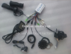
After replacing a failed controller (with one that was promised to be SW900-compatible, but really isn't), I decided to wire in the lights to the (battery voltage) 'lights' output of the controller, through a 48V->12V DC-DC converter. Predictably, the lights are on whenever the controller is on, instead of being switchable by the UP-arrow.
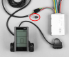
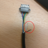
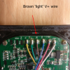
Since a lot of these LCDs have the extra 'LIGHTS' connector with the brown and white wires, I wanted to look into how to use them. Since the manuals offer no help, I thought I'd ask here before trying to figure it out with a voltmeter. So, the questions are:
1. Is the voltage regulated, and does it have a cut-off?
2. Is the current regulated and how much can safely be drawn (looks like at least a couple of amps - see below)?
3. Is it best to just use the voltage through a divider to switch a relay?
4. Does anyone have a bike that has this wired up and can provide a wiring diagram?

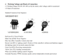
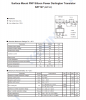
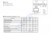
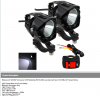
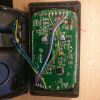
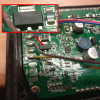
I opened up an old SW900 (pic below). From the transistor data sheet, it looks like it can take a decent load, but I don't know how much it would take without cooling. At the moment, I think the LCD light cable can power a 15W LED headlight. The battery voltage across those wires would be about 50V max, so the current would be 15/50 = 300 mA. The rear flashing light can be on with the controller (maybe through a 555 timer if I can't find a flashing red light. Does anyone concur?

Anyway, here are some pics, including an opened SW900 that had water damage. Interestingly, one of the vendors has a lamp just wired directly without further comment, but I wouldn't necessarily trust that.

1b-manual.png

5-SW900-pwr_trnstr2.png
6-SW900-pwr_trnstr.png

7-lights-15W.png

8-wired.png

1a-S830-connector.png

1-SW900-connector.png

4-SW900-open.png

3-SW900-board.png

2-SW-900-board.png

I think this is worth figuring out, since so many kits use these LCDs.

Thanks,
Bob
 

vfr400

Esteemed Pedelecer
Jun 12, 2011
9,822
3,986
Basildon
When the lights stay on, it's because the switching transistor is blown. Is there an inductor in your DC-DC converter. If so, it might have given out a kick.
 

8o887

Finding my (electric) wheels
Dec 17, 2019
7
0
Thanks, but no, it's not that. It did the same when the light was initially connected directly (it's good up to 60 V - I just want 12 V going around to the lights, and then 5 V for USB charging of the alarm and the GPS). Also, the power display on the SW900 is all over the place. It shows 2-300 W for a few seconds, even when idle, so I'm sure the controller is just not compatible, so I want to use the lights cable from the LCD.
 

vfr400

Esteemed Pedelecer
Jun 12, 2011
9,822
3,986
Basildon
The LCD works the lights completely independently of the controller, so there can be no compatibility issue with that function.
 

8o887

Finding my (electric) wheels
Dec 17, 2019
7
0
The LCD works the lights completely independently of the controller, so there can be no compatibility issue with that function.
Forgive me, but I don't think you've understood what I've said. If you look at the page from the manual (included in my post), it says that some controllers can switch the lights connector under software instruction from the LCD, but some can not.
It might help if I ask a specific question: How does one use the small Brown/White connector on the S866/SW900 LCDs as shown in my post?
 

vfr400

Esteemed Pedelecer
Jun 12, 2011
9,822
3,986
Basildon
The red wire going to the LCD has battery voltage, which is used to power the LCD when you press the power-on button. When you switch it on, the CPU in the LCD does two things: It latches the power on, and it switches a transistor to also latch it to the blue wire, which runs back to the controller and powers it. When you press the button/s for the lights, the CPU switches a different transistor to latch the red wire to the brown. The brown then has battery voltage to work the lights or anything else that you want to connect to it.

Some controllers have the brown wire (or other colour) in the controller. When you operate the button/s on the LCD/LED panel, the panel sends a communication signal to the CPU in the controller to tell it to switch on the transistor in the controller that latches the wire for the lights to the battery wire.

The lights that go up to 60v have their own buck converters in them so you don't need to use an external one. I'm pretty sure that they have inductors in them, which I would guess have blown your transistor. To connect anything with an inductor in it to a transistor, you need a protection diode, like this:
 
  • Informative
Reactions: danielrlee

8o887

Finding my (electric) wheels
Dec 17, 2019
7
0
Thanks...that makes a lot of sense. I appreciate your efforts with this - very impressive.
Just to be clear, I haven't yet connected anything to the LCD brown/white wires, which still switch as they should with the LCD backlight control. The controller was brand new when I metered the 'LIGHTS' power output, which was ON whether the LCD back-light was on or not. I understand that this is normal operation for many controllers.
What this comes down to is: When you say 'The brown then has battery voltage to work the lights or anything else that you want to connect to it. ', does that mean you can draw, say, half an amp at battery voltage from the LCD brown wire (~25 W)?
 

vfr400

Esteemed Pedelecer
Jun 12, 2011
9,822
3,986
Basildon
Thanks...that makes a lot of sense. I appreciate your efforts with this - very impressive.
Just to be clear, I haven't yet connected anything to the LCD brown/white wires, which still switch as they should with the LCD backlight control. The controller was brand new when I metered the 'LIGHTS' power output, which was ON whether the LCD back-light was on or not. I understand that this is normal operation for many controllers.
What this comes down to is: When you say 'The brown then has battery voltage to work the lights or anything else that you want to connect to it. ', does that mean you can draw, say, half an amp at battery voltage from the LCD brown wire (~25 W)?
You have to look at the tracks on the LCD to see whether the brown wire is connected to the same transistor output as the blue wire or whether it has its own transistor. Up 'til now, I've been speaking in principle from how other LCDs work. I've never studied the SW900.

I've never see an unswitched brown wire for lights on an LCD before. You get them on many controllers though.
 

8o887

Finding my (electric) wheels
Dec 17, 2019
7
0
It's got it's own transistor. It's the same basic circuit as the S866.
If I may ask, what applications have you encountered that used the brown wire, and what was the wiring?
 

vfr400

Esteemed Pedelecer
Jun 12, 2011
9,822
3,986
Basildon
It's got it's own transistor. It's the same basic circuit as the S866.
If I may ask, what applications have you encountered that used the brown wire, and what was the wiring?
All the ones I have seen are no-name Chinese ones. I've seen other SW900s, but never with the separate wires for the lights like yours, neither have I seen them on any Bigstone or Kingmeter LCD. I know some SW900s have the brown wire in the cable going to the controller, but I don't know what happens at the other end. I can only speak about the general situation. Many OEM bikes have the transistor for the lights in the controller because it's a common failure that I've had to repair many times.

I've just looked back through the thread. You show three different LCDs. It might help if you tell me which one you're talking about. I was assuming SW900. The first cheapo one you show, I am very familiar with, as i sold a load to forum members, and it has the separate brown and white wires for lights.
 
Last edited:

8o887

Finding my (electric) wheels
Dec 17, 2019
7
0
Ah, okay. I've got the SW900. The reason for citing the others is that the 'manual' pages and wording are identical for the Sxxx LCDs that I've seen, and the boards look very similar, so I wanted to emphasise the prevalence of the issue. I've searched for an answer, obviously, and only found one person saying that the brown wire is for a relay, but, while possible, I can't easily believe that, because thousands of people would be wiring in relays, and the wording surely wouldn't just stop at saying 'Lighting control's positive' - it would be easy to just use a transistor on the board as a relay and let it switch the power. Therefore, I assumed somebody must have just plugged an LED lamp into it by now, and the community would have known what to do ages ago. That was my thinking.
It also occurs to me that feeding the full battery voltage would only be justified if it was to keep the current down, which is what you'd design for if it was for running the lights at a dozen Watts.
You say you have sold many LCDs with the extra brown/white...what did they get used for?
 
Last edited:

vfr400

Esteemed Pedelecer
Jun 12, 2011
9,822
3,986
Basildon
You say you have sold many LCDs with the extra brown/white...what did they get used for?
They were sold as a set with controllers as an upgrade or replacement of crappier or broken ones. they were good at the time, but are not very good by today's standard.

Going back to basics. Unless the LCD or controller's manual tells you the rating of the brown wire, you have to treat it with caution. That's why people recommend a relay, but even with a relay, you need a protection diode. You need a protection diode when you connect anything with an inductor (coil) in it. If you know the rating and you have a light that's well within it, there's no problem. They use these things on many OEM bikes, though the lights are generally low power and crappy. I recommend to everyone who wants to fit anything that requires battery level supply to connect directly to the battery wires because you know that it can provide enough power without blowing a transistor.
 

8o887

Finding my (electric) wheels
Dec 17, 2019
7
0
I've got Arduino relays, which should be fine, but have a max switching voltage of 30V. So, with what I've got, I'd have to step down the brown wire to 12V to switch the relay, then run the light from the 'LIGHT' output from the controller. That's crazy.
I'll mount a switch in the handlebar.