Need help to Work out how many magnets are inside my hub motor

saneagle

Esteemed Pedelecer
Oct 10, 2010
4,197
2,078
Telford
I have this installed it came with my bike
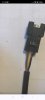
That's the pedal sensor. It has nothing to do with speed or speed calculation.

Your controller is using the motor hall sensors to calculate speed because either you have no speed sensor or it's faulty.
 

manman94

Pedelecer
Dec 7, 2023
116
2
60
Netherlands
Aha I see just been out and you are correct sir free wheeling I get no speed only when I pedal,I do not have such a wire on this controller only the pas sensor connector which has 3 wires is it possible I have the wires the wrong way round
 

manman94

Pedelecer
Dec 7, 2023
116
2
60
Netherlands
I have yellow black brown coming from the controller I know have but my old controller has red black and green,but what i can't see is the order of the wires coming from the PAS sensor .
 

saneagle

Esteemed Pedelecer
Oct 10, 2010
4,197
2,078
Telford
I have yellow black brown coming from the controller I know have but my old controller has red black and green,but what i can't see is the order of the wires coming from the PAS sensor .
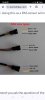
The speed sensor wire is the white one in the motor cable. If you have a sealed connector at the controller end of the motor cable, you can't see it. Some controllers double up the white wire and put it on a separate connector along with a red tv and black ground so that you can fit an external (to the motor) speed sensor.

If you don't see the white wire, you can open the controller to see it come out of the motor cable, where you can splice an external speed sensor into it.

Unless your motor is old, it should have a speed sensor in it. Sometimes the magnets come unstuck in Bafang motors, which you can fix by opening the motor and glue it back in place.

Your system is working as it is, though without correct distance calculation, so only mess about with it if you want to learn about how it works or if you need distance to be correct. I only explain all these things to help people understand how ebike systems work.
 
Last edited:

Nealh

Esteemed Pedelecer
Aug 7, 2014
20,135
8,230
60
West Sx RH
Yellow is the signal wire, Brown /5v & Black/ Gnd.
 

manman94

Pedelecer
Dec 7, 2023
116
2
60
Netherlands
Well from the controller it's brow black from left to right and the cable coming from the PAS is from left to right red black and blue .on my stock controller I don't have a white wire either but everything works with that no problem with speed sensor
 

flecc

Member
Oct 25, 2006
52,819
30,381
Whispering Ted Lowe: "For those watching in black and white, the pink (ball) is next to the green."
Poor Ted, that will forever haunt him.

Of course he was just assuming viewers knowledge of snooker, since the green was on its spot so easily identified.
.
 

saneagle

Esteemed Pedelecer
Oct 10, 2010
4,197
2,078
Telford
Poor Ted, that will forever haunt him.

Of course he was just assuming viewers knowledge of snooker, since the green was on its spot so easily identified.
.
But how would you know that the brown wasn't on the green's spot.
 
  • Agree
Reactions: flecc

saneagle

Esteemed Pedelecer
Oct 10, 2010
4,197
2,078
Telford
The one circled is the one I've connected to the pas sensor,I think maybe there wrong .
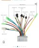
You must have connected the pedal sensor to the correct connector, otherwise your motor wouldn't run on after you stopped pedalling. That never happens with a throttle. Also, if you had connected the pedal sensor to the throttle, your motor's speed would depend on how fast you pedal, and the pedal assist levels in the LCD would probably have no effect.
 

manman94

Pedelecer
Dec 7, 2023
116
2
60
Netherlands
You can see on the diagram my doubt although this not my controler it has exactly the same number of plugs and wires ,you see in this picture the throttle is the exact same as the controller I have now on the bike but i had no diagram of the controller now in my bike .
So I'm guessing the picture with diagram showing the names of the wires are different than mine
 

Attachments

saneagle

Esteemed Pedelecer
Oct 10, 2010
4,197
2,078
Telford
You can see on the diagram my doubt although this not my controler it has exactly the same number of plugs and wires ,you see in this picture the throttle is the exact same as the controller I have now on the bike but i had no diagram of the controller now in my bike .
So I'm guessing the picture with diagram showing the names of the wires are different than mine
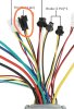
Did you have to cut the connector off because pedal sensors are normally female connectors with male pins and the controller side is male with female pins, like shown in that diagram?
 

manman94

Pedelecer
Dec 7, 2023
116
2
60
Netherlands
Yes the yellow black brown that says throttle I cut that off and changed to a connector to same as the connector that's PAS.
As described in the diagram above I know from my sensor by the pedal with 12 magnets I know that the wires are red black and blue that have to be connected to a 3 pin connector on the controler ,I read that can sometimes be the red whites and black but can also be yellow brown and black not necessarily in that order but those colours please check the photos I found
 

Attachments

saneagle

Esteemed Pedelecer
Oct 10, 2010
4,197
2,078
Telford
The image above is the same as the picture above with diagram only with the connector having been swapped.
The designations in the image in post#36 are correct. I thought that you said it was all working earlier. what problem are you wanting to solve?
 

manman94

Pedelecer
Dec 7, 2023
116
2
60
Netherlands
Yes it's working but if I push the bike it does not give a reading on the display as with my old controller and I have to put the amount of magnets in settings on the display which is P7 I have had to put 80