

dear all, sorry for one further noob question, I've installed a bpm code 10 (in a 20 wheel) in a hase tagun (changed my mind back from a full mountainbike because the bpm came in a 20 wheel and the hase was lying around gathering dust with its two OK mechanical disks and all, and just seemed so perfect for it). But now because of this I need a 48V battery to give 393RPM in the code 10 BPM (I say that as I if know what I'm talking about, and not just repeating what I read somewhere). I have had a look on hobbyking at lipos - but, if you had this kind of spec and wanted a bpm code 10 to push a 100kg rider around twenty to thirty hilly miles in a recumbent, what kind of 48V battery would you get? many thanks for the help (for what its worth - if any of you are considering doing the same - go for it, so far it's only involved a cassette removal tool and has been astonishingly simple, easier than building a pc, completely modular, nothing to it, and interesting)
48V battery
- Thread starter derf
- Start date
D
Deleted member 4366
Guest
Where did you get 393 rpm from? A code 10 is 315 rpm, so if you went from 36v to 48v, that would be 420 rpm. With a charged battery, that would increase to 462 rpm, or 24 mph in a 20" wheel. If you have it already, test it at whatever voltage you've got, and let us know the results. It doesn't seem to be an exact science re markings and actual speed. You might get a surprise.
many thanks, I got two of theseWhere did you get 393 rpm from? A code 10 is 315 rpm, so if you went from 36v to 48v, that would be 420 rpm. With a charged battery, that would increase to 462 rpm, or 24 mph in a 20" wheel. If you have it already, test it at whatever voltage you've got, and let us know the results. It doesn't seem to be an exact science re markings and actual speed. You might get a surprise.
http://www.hobbyking.com/hobbyking/store/__20647__zippy_flightmax_8000mah_6s1p_30c_usa_warehouse_.html
do you think they'd be any good in series? high chool physics is along time ago, when batteries are in series what is capacity (i.e. at 44V will it be 8 or 16 Ah?)
I got the 393rpm herehttp://endless-sphere.com/forums/viewtopic.php?f=3&t=35323
I'm just back from work and reading the mixed reviews of the batteries makes one wonder if its any good, though it is cheap (£130 for two 22v 8 AH), will complete installing soon as I have batteries and give detailed feedback re speed, 24 mph would be perfect
D
Deleted member 4366
Guest
Those batteries are pretty good. They'll give you all the current you want. In series, they're still 8ah, so they won't take you far - probably about 15 to 20 miles if you don't go nuts. On the other hand, maximum power will empty them in about 15 minutes.
You need to be very disciplined in using them. You can get some protection from your controller if you set it to 48v, which should make it cut off at about 38.5v - dangerously close to their 36v absolute minimum. You need a voltmeter or better still, a wattmeter to monitor them. A wattmeter will tell you when you're getting towards the 8aH. A voltmeter will tell you when you need to get off and push. Once they get down to 44v, they start to accelerate down rapidly. Whatever you do, don't try and eek out the last bit. In no time at all, they'll go below the minimum, and then you'll have two very expensive bricks. I'd use about 43v as a minimum.
You need to be very disciplined in using them. You can get some protection from your controller if you set it to 48v, which should make it cut off at about 38.5v - dangerously close to their 36v absolute minimum. You need a voltmeter or better still, a wattmeter to monitor them. A wattmeter will tell you when you're getting towards the 8aH. A voltmeter will tell you when you need to get off and push. Once they get down to 44v, they start to accelerate down rapidly. Whatever you do, don't try and eek out the last bit. In no time at all, they'll go below the minimum, and then you'll have two very expensive bricks. I'd use about 43v as a minimum.
D
Deleted member 4366
Guest
Speed in a 20" wheel with 12S would be about 420 rpm, which is about 24 mph - just about right for its power.
many thanks for the helpful info, all is gradually becoming clear (30C meaning 30 times 8 meaning 240A or about 500 watt at 22.2V - but apparently the battery will last more charge cycles if one discharges at lower rates - say 20C?). is there any way to use the controller to set cut off voltage at 43V instead of 38.5V? Also is this http://www.hobbyking.com/hobbyking/store/uh_viewItem.asp?idProduct=23590Those batteries are pretty good. They'll give you all the current you want. In series, they're still 8ah, so they won't take you far - probably about 15 to 20 miles if you don't go nuts. On the other hand, maximum power will empty them in about 15 minutes.
You need to be very disciplined in using them. You can get some protection from your controller if you set it to 48v, which should make it cut off at about 38.5v - dangerously close to their 36v absolute minimum. You need a voltmeter or better still, a wattmeter to monitor them. A wattmeter will tell you when you're getting towards the 8aH. A voltmeter will tell you when you need to get off and push. Once they get down to 44v, they start to accelerate down rapidly. Whatever you do, don't try and eek out the last bit. In no time at all, they'll go below the minimum, and then you'll have two very expensive bricks. I'd use about 43v as a minimum.
a good charger for £40 or should one go all the way and get a FMA PL6 if one wanted to recharge in a few hours?
D
Deleted member 4366
Guest
That's probably quite a good charger, but might be over-kill. Like most lipo chargers, it needs a 12v power supply. To charge at 400w, you'll need a very expensive one. You can make a power supply out of any old one out of a PC. You can often pick them up at car boot sales for £1, but they sag a bit, so charging two packs in parallel at 4A will be about the maximum. You can use server power supplies too, which give about 30A for fast charging.
It's always best to charge slowly if you can. It's better for the cells and safer.
It is possible to raise the low voltage control point. In the corner of the controller are three 1% resistors. There's 15k (1502) and 1K2 (1201) that make the 48v divider. The jumper brings a 43K (4302) in parallel with the 15K one to bring it down to 11K for 36v. I calculated the trip point at 2.86v to the CPU, so you need to change the value of the 1.2k one to split 43v down to 2.86, so we have (R x 43)/ (R + 15K) = 2.86, so R = 1.06K.
We therefore need to solder another resistor to the 1.2K one that changes its value to 1.06K.
1/r +1/1.2 = 1/1.02 therefore r = 6.8K.
So, you get a 6.8k resistor from Maplin and solder each end to the pads of the 1.2K one and you have it. Get a 1% 1/4w one if you can.
Perhaps somebody can check my maths to make sure, but it looks about right to me.
many thanks for that (had a feeling this wouldn't be simple). is the corner you are referring to the bottom left hand corner (I see what seems one resistor next to the two brown capacitors?). or is it a different corner?That's probably quite a good charger, but might be over-kill. Like most lipo chargers, it needs a 12v power supply. To charge at 400w, you'll need a very expensive one. You can make a power supply out of any old one out of a PC. You can often pick them up at car boot sales for £1, but they sag a bit, so charging two packs in parallel at 4A will be about the maximum. You can use server power supplies too, which give about 30A for fast charging.
It's always best to charge slowly if you can. It's better for the cells and safer.
It is possible to raise the low voltage control point. In the corner of the controller are three 1% resistors. There's 15k (1502) and 1K2 (1201) that make the 48v divider. The jumper brings a 43K (4302) in parallel with the 15K one to bring it down to 11K for 36v. I calculated the trip point at 2.86v to the CPU, so you need to change the value of the 1.2k one to split 43v down to 2.86, so we have (R x 43)/ (R + 15K) = 2.86, so R = 1.06K.
We therefore need to solder another resistor to the 1.2K one that changes its value to 1.06K.
1/r +1/1.2 = 1/1.02 therefore r = 6.8K.
So, you get a 6.8k resistor from Maplin and solder each end to the pads of the 1.2K one and you have it. Get a 1% 1/4w one if you can.
Perhaps somebody can check my maths to make sure, but it looks about right to me.
D
Deleted member 4366
Guest
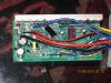
It looks like they've changed it again. I'm pretty sure that the one marked 3302 (33K) is one of them R3. I think the other one is R20 the little one at right angles to it. The markings are too small to read. Can you tell me what they are. To put the cut-off at 2.5v (middle of the range 0 to 5v), it would have to be 2.3k, so perhaps marked 242. Then we have to redo the above calculation.
Is the blue wire next to R3 the return from the display wire, i.e. the one you have to short to the red one?
Is the blue wire next to R3 the return from the display wire, i.e. the one you have to short to the red one?
Many thanks, will look soon as I'm back (away two weeks with work), would seem an almighty simplification from theseIt looks like they've changed it again. I'm pretty sure that the one marked 3302 (33K) is one of them R3. I think the other one is R20 the little one at right angles to it. The markings are too small to read. Can you tell me what they are. To put the cut-off at 2.5v (middle of the range 0 to 5v), it would have to be 2.3k, so perhaps marked 242. Then we have to redo the above calculation.
Is the blue wire next to R3 the return from the display wire, i.e. the one you have to short to the red one?
http://www.hobbyking.co.uk/hobbyking/store/uh_viewItem.asp?idProduct=44508
if it were possible to get the controller to automatically protect the batteries
D
Deleted member 4366
Guest
The S12S controller has an adjustable LVC via a setting in the LCD.
I've been looking at your photo again. There's a couple of blank pads next to R3 marked R36. That will be to add a resistor to change it to 36v. They've also provided a position to solder in a normal resistor marked R2. If the top end of that is ground, that's specifically for increasing the LVC point.
I've been looking at your photo again. There's a couple of blank pads next to R3 marked R36. That will be to add a resistor to change it to 36v. They've also provided a position to solder in a normal resistor marked R2. If the top end of that is ground, that's specifically for increasing the LVC point.
sounds great - it means getting an s12s controller, but adds torque simulation, I gather from your previous post it does 23 amps at 36v, is it OK for 44V and 48V?The S12S controller has an adjustable LVC via a setting in the LCD.
I've been looking at your photo again. There's a couple of blank pads next to R3 marked R36. That will be to add a resistor to change it to 36v. They've also provided a position to solder in a normal resistor marked R2. If the top end of that is ground, that's specifically for increasing the LVC point.
many thanks again (i found this article http://www.electricbike.com/sine-wave/ that explains some basics in case anyoien else reaidng this hadnt quite got teh gist of FET's yet), the conotroller is easy to order on BMS (and cheap) but comes without an LED and Suga (from BMS) perhaps understandably stopped chatting to me when i asked about when i started asking about this and stuff like LVC, which LED would you recomend? the original kit with teh KU123 didnt have an LEDThe S12S controller has an adjustable LVC via a setting in the LCD.
I've been looking at your photo again. There's a couple of blank pads next to R3 marked R36. That will be to add a resistor to change it to 36v. They've also provided a position to solder in a normal resistor marked R2. If the top end of that is ground, that's specifically for increasing the LVC point.
D
Deleted member 4366
Guest
The S12S is dual voltage 35/48v. That must be a good article that you linked to above because he mentioned me in it. I specially like the diagram that shows how the PWM works to make the sine-wave.
thanks, which LED would you recomend for teh S12s?The S12S is dual voltage 35/48v. That must be a good article that you linked to above because he mentioned me in it. I specially like the diagram that shows how the PWM works to make the sine-wave.
D
Deleted member 4366
Guest
The LCD3 is the best one, then the LCD1. The LED ones are no good because you can't change any parameters.
many thanks, that's extremely helpful, will have another look on bmsbattery..The LCD3 is the best one, then the LCD1. The LED ones are no good because you can't change any parameters.
Related Articles
-
 MTF Enterprises announces acquisition of EMU Electric Bikes
- Started by: Pedelecs
-
 Wisper 806T folding bike wins Which? ‘Best Buy’
- Started by: Pedelecs
-
 Sustrans calls for protected cycle lanes
- Started by: Pedelecs
-
 Amazon launch their first UK e-cargo micromobility hub
- Started by: Pedelecs
