Tbh knowing some of the cells are self discharging then I doubt it will remain balanced at all, so you might as well continue going to 4.2v per cell.
Because chargers only use cc/cv they can't regulate cells voltages, these can only remain stable and balanced if all are good to start with and remain good.
I think it is the case that 30Q is for sur now deemed not to be a good choice to select over other cells.
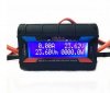
The 3 Blue marked VR's are for voltage regulation and current regulation, whether they actual will do so I don't know. The one marked VR4 at the top on it's own will be the main one to try and adjust for voltage. If you do try it make a note of how much of a turn you make, a 1/4 turn will usually make a significant voltage change one way or the other (anti c/w to go lower 7 c/w to go higher). I set my meter up with probes on the charger output connector and watch the meter whilst making adjustments to the VR.
The VR/C5 (C5 may denote current 5a ) near the coil is used to adjust the charge current as the the PCB track has continuity to the shunt, again once and if you try adjusting voltage set your meter to read current and adjust the current VR/C5.
On the meter leave the Black in the com & put the Red in the 10adc socket, turn the dial to 10A reading and place your probes on the charger output connector as you would to test voltage ( you may get a small light spark as you touch the Black probe to gnd ). You meter should read 5a and it should decrease as you turn VR/C5 anti c/w.
Because chargers only use cc/cv they can't regulate cells voltages, these can only remain stable and balanced if all are good to start with and remain good.
I think it is the case that 30Q is for sur now deemed not to be a good choice to select over other cells.
The 3 Blue marked VR's are for voltage regulation and current regulation, whether they actual will do so I don't know. The one marked VR4 at the top on it's own will be the main one to try and adjust for voltage. If you do try it make a note of how much of a turn you make, a 1/4 turn will usually make a significant voltage change one way or the other (anti c/w to go lower 7 c/w to go higher). I set my meter up with probes on the charger output connector and watch the meter whilst making adjustments to the VR.
The VR/C5 (C5 may denote current 5a ) near the coil is used to adjust the charge current as the the PCB track has continuity to the shunt, again once and if you try adjusting voltage set your meter to read current and adjust the current VR/C5.
On the meter leave the Black in the com & put the Red in the 10adc socket, turn the dial to 10A reading and place your probes on the charger output connector as you would to test voltage ( you may get a small light spark as you touch the Black probe to gnd ). You meter should read 5a and it should decrease as you turn VR/C5 anti c/w.