

I have fitted a brain power controller and display to a Dawes Swift with a Dapu mid mount motor. The dawes speed sensor fits to the rear wheel and has 2 wires and the pedal assist is built into the motor and has 4 wires. I can only get the bike to run with a throttle and the speed displayed on the screen is only there when the motor is turning and is based on motor speed and not wheel speed. Is there any way to get the speed reading from the wheel and if the padal assist is faulty can it be fixed or replaced with some other type?
Brain power controller
- Thread starter DJG
- Start date
You need to connect the white wire in the motor connector to the speed sensor. One wire goes to the white and the other probably to any 5v. If that doesn't work, connect the second wire to ground.
You'll have to find some way to bodge a normal pedal sensor onto the crank if you want pedal assist.
You'll have to find some way to bodge a normal pedal sensor onto the crank if you want pedal assist.
You need to connect the white wire in the motor connector to the speed sensor. One wire goes to the white and the other probably to any 5v. If that doesn't work, connect the second wire to ground.
You'll have to find some way to bodge a normal pedal sensor onto the crank if you want pedal assist.
It's not using any speed sensor in the motor. Instead, it's picking up the speed signal from a motor hall sensor. Maybe your motor doesn't have a speed sensor in it. You can check by measuring the voltage on the white wire while you turn the wheel backwards. It would pulse once or 6 times per rotation.
If the white wire doesn't pulse, you can use your external one, like I explained above. It makes no difference whether you leave the white wire connected or not because if it doesn't pulse, it's not connected to anything in the motor.
If the white wire doesn't pulse, you can use your external one, like I explained above. It makes no difference whether you leave the white wire connected or not because if it doesn't pulse, it's not connected to anything in the motor.
Hi
I have checked the white wire from the motor and I get a pulse of voltage when turning the wheel backwards. I also checked for continuity across the red and black wires from the speed sensor which showed continuity when the magnet passed the sensor.
Can this be used to give a speed reading when wired into the controller?
One wire to white, the other to 5v. If that doesn't work, the second wire goes to ground. Don't forget that you need to set the number of pulses in the settings (P07) to 1. If it's zero, the controller will probably use a motor hall instead.The speed sensor only has 2 wires
Put the other wire to ground, and see if it pulses up or down. Also, the way it is now, check whether it pulses to zero volts when the magnet goes past. Basically, with the white wire not connected, measure it on the controller side. if it measures zero volts, you connect the second wire to 5v and it'll pulse up, and if it measures 5v, you connect the other to ground and it'll pulse down.The white wire is showing 5v I thought it was pulsing when checked before
Last edited:
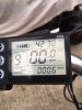
Connected the white of controller to black of speed sensor and an earth to red of speed sensor and I get a reading on the display, going to road test and check speed against a gps and adjust P18 to suit. Have ordered pedal assist sensor and magnet disc and will fabricate it to fit and hopefully all will then work.
Many thanks for your assistance.
Many thanks for your assistance.
Thanks for that. It's the first time somebody has confirmed the wiring despite about 10 people had the same problem.Connected the white of controller to black of speed sensor and an earth to red of speed sensor and I get a reading on the display, going to road test and check speed against a gps and adjust P18 to suit. Have ordered pedal assist sensor and magnet disc and will fabricate it to fit and hopefully all will then work.
Many thanks for your assistance.
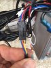
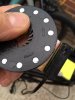
Hi there, I got a pedal assist disc and sensor and have tried it before making any brackets to fit it and have connected it as per photos, I have a 5v feed to the red and take a neutral from the black and when moving the disc across the sensor get a pulse of 5v on the blue but the motor doesn't turn, I have set P13 to 12 . Should the motor attempt to turn?
Attachments
-
 56.1 KB Views: 8
 -
 52.7 KB Views: 6
 -
 46.6 KB Views: 6
Set it to 6 if you can. It's always the 12 pole magnet discs that cause problems. My theory is that there's not enough gap between them so the next magnet is switching it back on before it has a chance to switch off or something like that. I'm not saying this is your issue, but it's easy to test by pushing out some of the magnets. You can always put them back in afterwards.How many pole is the best, and do I leave the magnet setting on 12 when using six magnets?

Related Articles
-
 MTF Enterprises announces acquisition of EMU Electric Bikes
- Started by: Pedelecs
-
 Wisper 806T folding bike wins Which? ‘Best Buy’
- Started by: Pedelecs
-
 Sustrans calls for protected cycle lanes
- Started by: Pedelecs
-
 Amazon launch their first UK e-cargo micromobility hub
- Started by: Pedelecs
