

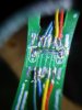
here's a photo of the other side of the circuit board
Attachments
-
 1.4 MB Views: 11
You can see one end of the reed switch connected to black and the other end to white. it's weird that it has so many wires and solder joints in it because it only needs two wires.here's a photo of the other side of the circuit board
 www.electrokit.com
that would be an easier option than the rig that's been put together on the circuit board....I'm not up on all these types of reed switches but it sounds better than what I have set up and a lot less hassle, I will think how I'm going to do this.....will I have to use that circuit board?You can see one end of the reed switch connected to black and the other end to white. it's weird that it has so many wires and solder joints in it because it only needs two wires.
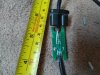
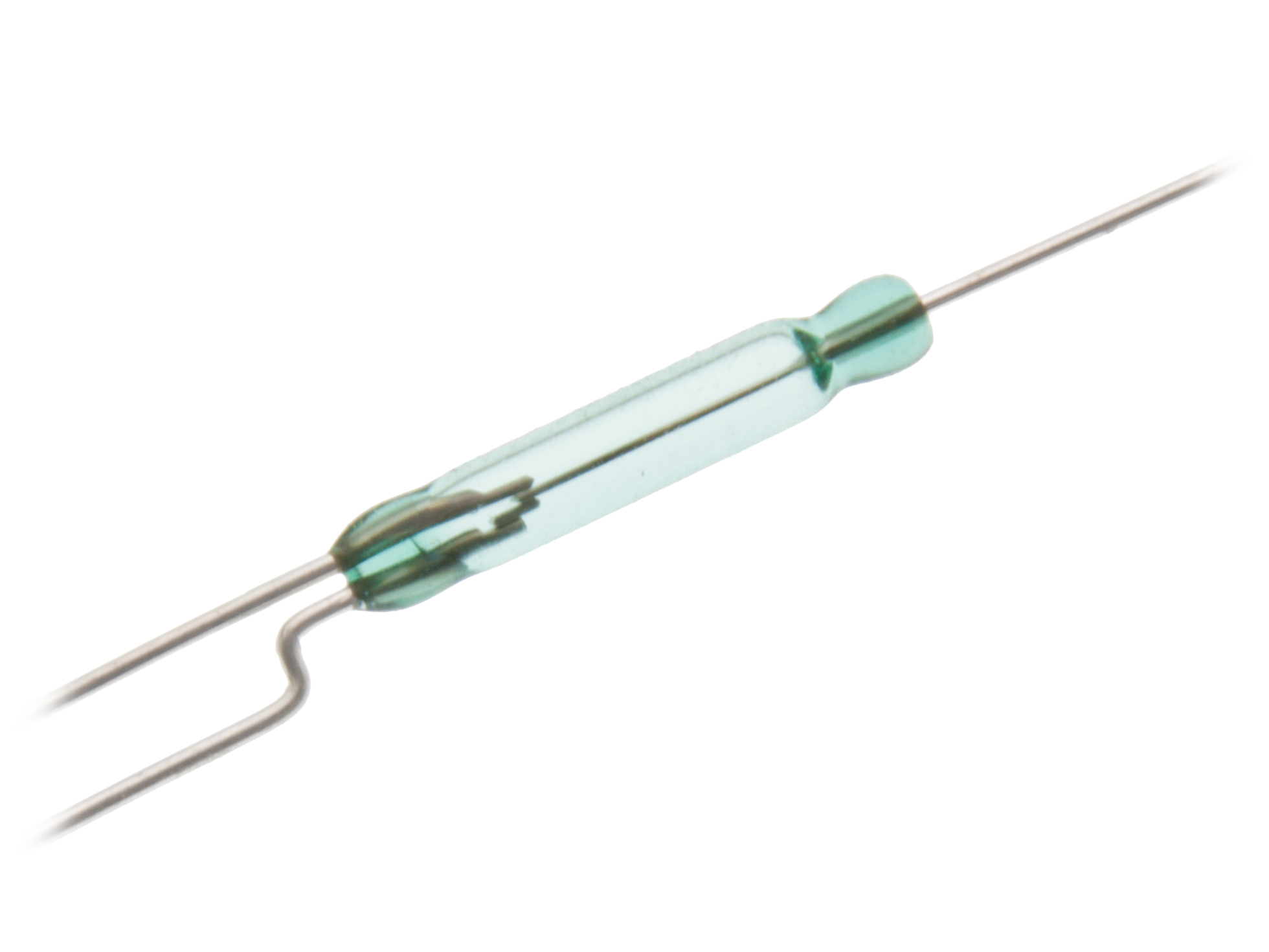
You can make your own cable brake switches by taping a reed switch to your crossbar under one of the open cables, then stick or heatshrink one of those magnets to the cable, so that the magnet moves onto or away from the switch when the cable moves. Some reed switches are naturally on (NC)and get switched off by a magnet, others are the other way round (NO). Some are both, like this one depending which of the two wires you connect:
Buy Reed switch 1p NC/NO 0.25A 15-20AT at the right price @ electrokit
75.00 SEK * Reed switch 1p NC/NO 0.25A 15-20AT original Littelfuse brand Reed switch 1-pole. The contact has separate outputs for normally closed and normally open. The available from Electrokit
You get the error code when the switch is on before you switch the controller on. it's telling you that the switch is stuck on, but if everything is assembled correctly, the switch will sort itself out as soon as you operate the brake. normally, when you get the error code with one of those switches, you switch off the controller, operate the brake a couple of times to get the magnet in its home position, then switch on again.that would be an easier option than the rig that's been put together on the circuit board....I'm not up on all these types of reed switches but it sounds better than what I have set up and a lot less hassle, I will think how I'm going to do this.....will I have to use that circuit board?
The "sensor" on this PCB is a reed relay, you can see it clearly in the first photo. Probably no Hall effect sensors.....What's on the other side. I'd expect to see a hall sensor or two.
the switch seems open circuit at the moment on the reed switch, I did a continuity test and got no audible beep to show it was closed, even when I waved a magnet in close proximity to it....here's a closer picture of the reed switch.You get the error code when the switch is on before you switch the controller on. it's telling you that the switch is stuck on, but if everything is assembled correctly, the switch will sort itself out as soon as you operate the brake. normally, when you get the error code with one of those switches, you switch off the controller, operate the brake a couple of times to get the magnet in its home position, then switch on again.
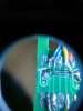
Hi AndyThe "sensor" on this PCB is a reed relay, you can see it clearly in the first photo. Probably no Hall effect sensors.....
As its very unlikely both will be used on the same PCB.....
The usual type of reed switch, is a normally open contact, which closes when a magnet comes close.Hi Andy
I can only see the reed switch that Vfr400 pointed out, and the two magnets on each cable that's all.
hopefully once I put it back together tonight it should work.
but!......does the way you put the magnets inside the multi box matter? do the magnets have to be put in with both polarity's opposite and attracting? or opposite each other with opposing polarity's repplelling each other?
OK thanks for the info Andy, it look`s like the fault is intermittent now when I put it together, another thing maybe is the magnetic field that I subjected the reed switch to may be to strong for it and may have pushed it beyond it's tolerance.....who knows? I will try another reed switch and see how it pans out.The usual type of reed switch, is a normally open contact, which closes when a magnet comes close.
A multi meter on ohms, placed across the reed switch should tell you if it is operating correctly or not.
If I remember correctly, possibly some reed switches are magnet polarity sensitive, but that is very seldom.
Another possibility, is that the contacts have had too much current, and are now welded together. But they are cheap and easily replaced....Try ebay or a hobby shop!
Regards
Andy
As I said above, reed switches come in three flavours: NO = normally open; NC = normally closes; and NC/NO = both depending on which wire you connect.OK thanks for the info Andy, it look`s like the fault is intermittent now when I put it together, another thing maybe is the magnetic field that I subjected the reed switch to may be to strong for it and may have pushed it beyond it's tolerance.....who knows? I will try another reed switch and see how it pans out.
Best wishes.OK thanks for the info Andy, it look`s like the fault is intermittent now when I put it together, another thing maybe is the magnetic field that I subjected the reed switch to may be to strong for it and may have pushed it beyond it's tolerance.....who knows? I will try another reed switch and see how it pans out.


